Excavation tool

一种工具、刀片的技术,应用在挖掘工具领域,能够解决挖掘性能易受损、挖掘效率下降、工具寿命缩短等问题,达到抑制挖掘孔径缩小、降低挖掘费用、实现工具寿命的效果

Inactive Publication Date: 2014-07-30
RYUKI PRECISION TOOLS CO LTD
View PDF14 Cites 4 Cited by
  • Summary
  • Abstract
  • Description
  • Claims
  • Application Information

AI Technical Summary

Problems solved by technology

[0006] However, the wear or abrasion of the tip portion of such digging blades is not uniform
For example, among the plurality of excavating blades implanted in the front end of the tool body, especially the excavating blade implanted in the measuring portion on the outer peripheral side of the tip end, the surface facing the outer peripheral side wears or wears significantly and becomes unilateral. Due to the wear pattern of wear, the excavation performance is easily impaired, which is an important cause of the decline in excavation efficiency. In addition, the wear of the excavation blade in the measurement part results in a reduction in the excavation hole diameter, which has a significant impact on the life of the tool.
[0007] Moreover, the eccentric wear of the cutting edge of the excavating blade is particularly noticeable under conditions where the ground or the rock disk is hard and the cutting edge is severely worn, and the life of the tool is shortened and the cost of excavation increases.
In addition, in order to restore the excavation performance, it also requires cost and time to regrind the cutting edge of the excavation blade.
In addition, if the excavation tool reaches the tool life before the excavation hole reaches the desired depth, the replacement of the tool body requires time, labor, and cost.
In addition, if excavation is continued in a state where the excavation performance is impaired due to wear or wear of the cutting edge, wear or damage will occur on the tool body, or a large load will be applied to the excavation device.

Method used


Image

  • Excavation tool
  • Excavation tool
  • Excavation tool

Examples


Embodiment Construction

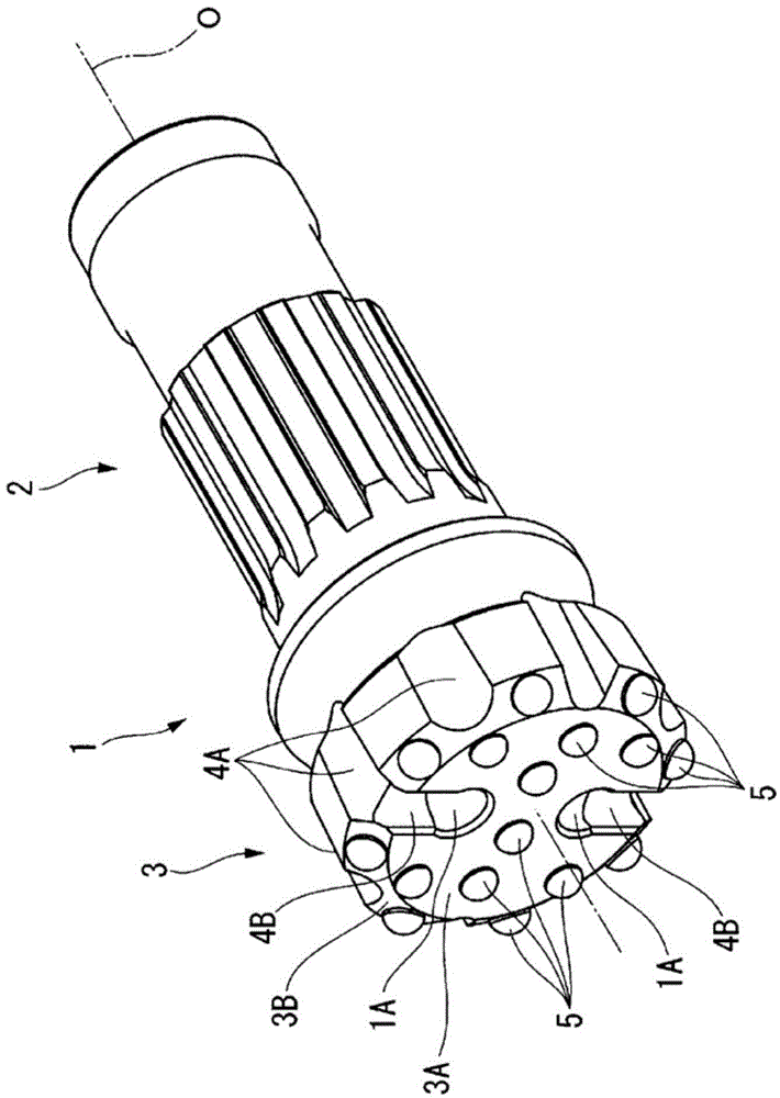
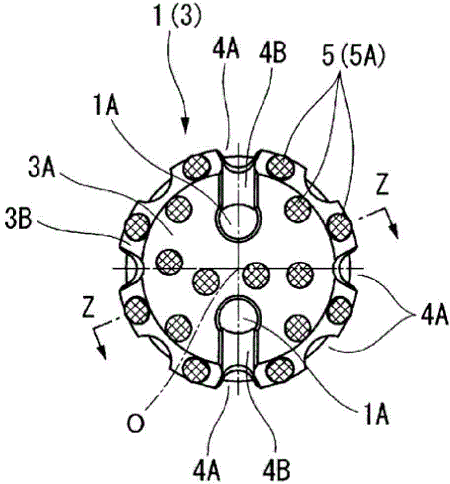
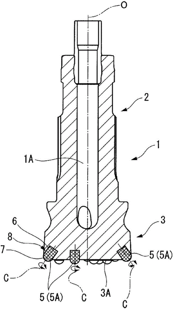
[0071] Figure 1 to Figure 5B It is a figure which respectively shows 1st - 4th embodiment of this invention. In these embodiments, the tool body 1 is formed of steel or the like, such as figure 1 As shown, it is the top part ( figure 1 Middle is the left part. Figure 2A to Figure 5B The lower side part in each B figure) is a large diameter and as it moves toward the rear end side (in figure 1 Middle is the right side. Figure 2A to Figure 5B Each B figure is the upper side), and the outer diameter gradually decreases in a substantially multi-stage cylindrical shape centered on the axis O.

[0072] The rear end portion of the tool body 1 is a shank 2 . The shank 2 is attached to an unillustrated down-the-hole hammer, whereby the tool body 1 receives an impact force from the down-the-hole hammer toward the tip side in the axis O direction. Furthermore, an excavating device is connected to the rear end of the down-the-hole hammer via an excavating rod not shown, and the t...


PUM


Abstract

In this excavation tool, an embedding hole (8) is provided piercing the tip of a tool main body (1) that rotates around an axis line (O) and progresses towards the tip in the axis line (O) direction, an excavation tip (5A) wherein a cylindrically-contoured embedding section (6) and a blade tip section (7) are integrally formed is inserted into the embedding hole (8) causing the embedding section (6) to be inserted into the embedding hole (8) and the blade tip section (7) to protrude from the embedding hole (8), and the excavation tip (5A) is attached in a manner so as to be able to rotate around the center line (C) of the embedding section (6) during excavation and in a manner so as to be prevented from dislocating towards the tip in the direction of the center line (C).

Description

technical field [0001] The present invention relates to an excavating tool, which is provided with a buried hole at the top end of the tool body that rotates around an axis and advances toward the top end side of the axis. The protruding form is buried in this buried hole. [0002] This application claims priority based on Patent Application No. 2011-262526 filed in Japan on November 30, 2011 and Patent Application No. 2012-251357 filed in Japan on November 15, 2012, and uses the contents thereof here. Background technique [0003] As such an excavating tool, for example, as described in Patent Documents 1 and 2, the following excavating tools are known: a tool body composed of steel or the like in which a plurality of excavating blades made of sintered alloys such as cemented carbide are attached to the tip. The device is attached to the tip of the digging rod or the tip of the digging rod, and the rotation force around the axis of the tool body and the thrust toward the t...

Claims


Application Information

Patent Timeline
Patent Type & Authority Applications(China)
IPC IPC(8): E21B10/46
CPCE21B10/633E21B10/43E21B10/54E21B10/38
Inventor 日和佐米雄久田仁也中村和由
Owner RYUKI PRECISION TOOLS CO LTD
Why Eureka
Try Eureka