
A punching force unloading device for micro punching equipment

A technology of unloading device and punching force, which is applied in metal processing equipment, forming tools, manufacturing tools, etc., can solve the problems of being unable to bear the punching force, etc., to protect the precision mobile platform, uniformly distribute the bearing capacity, and ensure punching accuracy Effect

Inactive Publication Date: 2016-03-02
DALIAN UNIV OF TECH
View PDF6 Cites 0 Cited by
  • Summary
  • Abstract
  • Description
  • Claims
  • Application Information

AI Technical Summary

Problems solved by technology

However, the precision moving platform cannot bear the punching force during the punching process, so after using the precision moving platform to realize the matching of the punch and die, it is necessary to use a device to unload the punching force during the punching process

Method used


Image

  • A punching force unloading device for micro punching equipment
  • A punching force unloading device for micro punching equipment
  • A punching force unloading device for micro punching equipment

Examples


Embodiment Construction

[0011] The present invention will be further described in detail below in conjunction with the accompanying drawings and preferred embodiments. In this embodiment, the micro electric discharge machining technology is used to prepare the convex and concave molds of complex shapes online, and the precision moving platform is used to realize the coupling of the convex and concave molds.

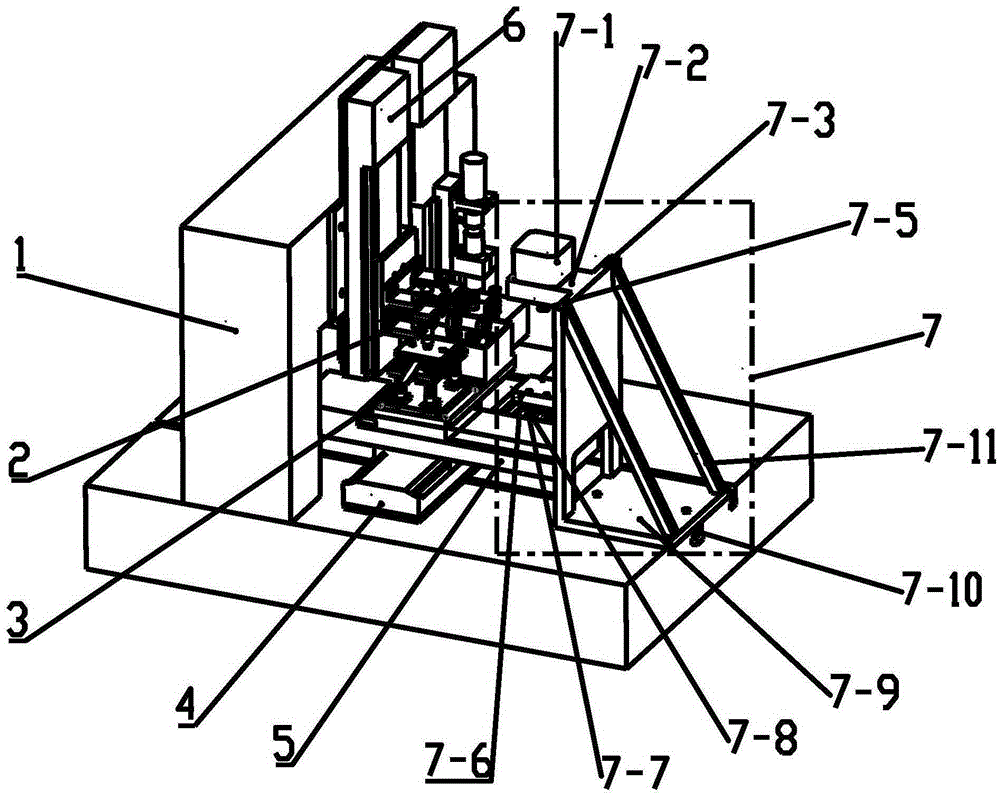
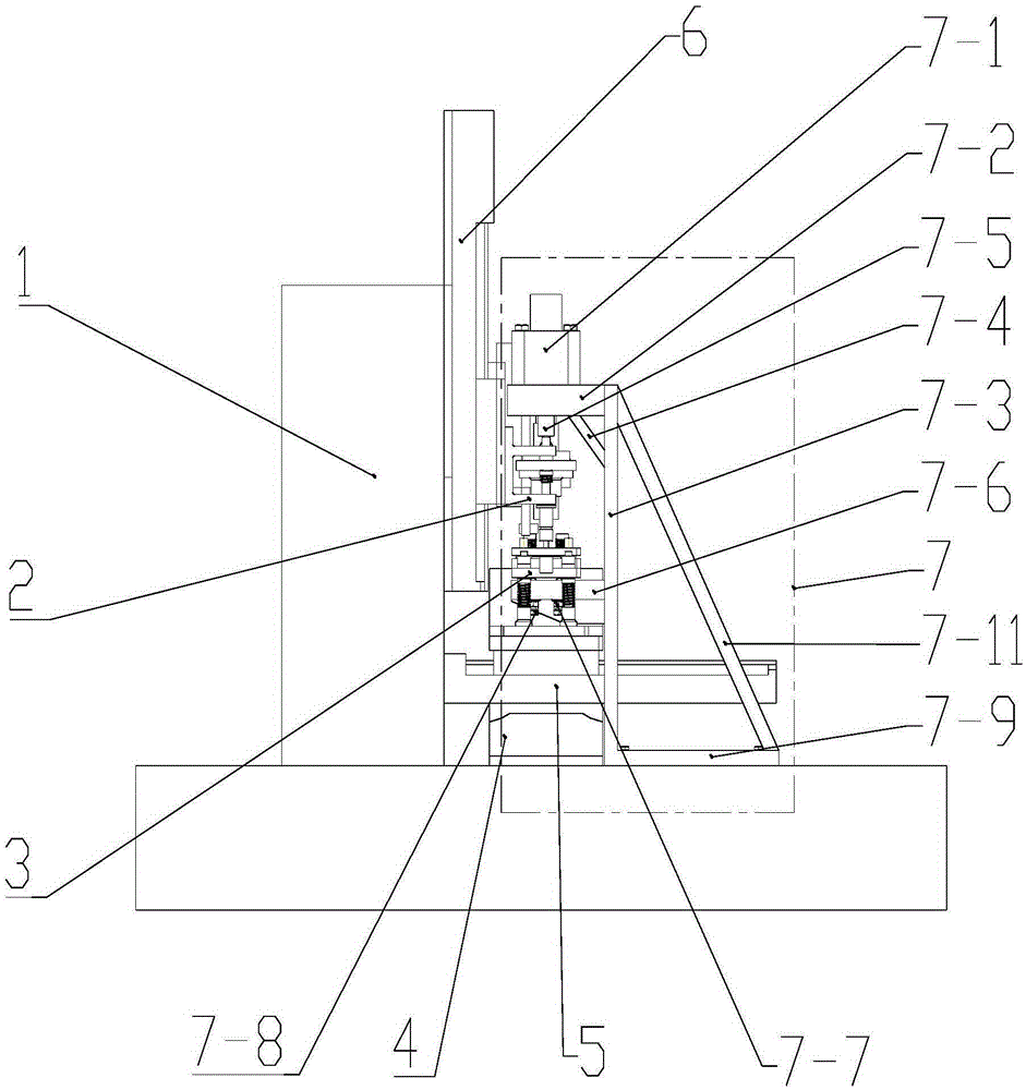
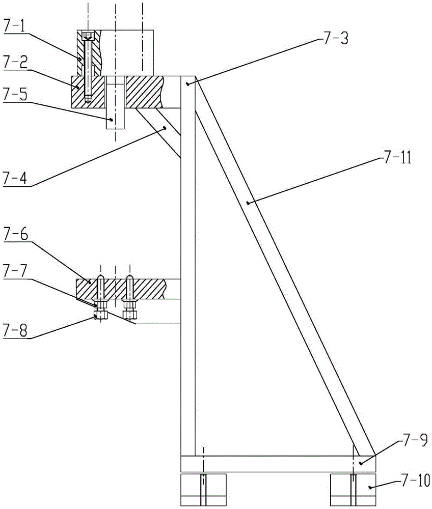
[0012] like Figure 1~3 As shown, the punching force unloading device 7 is installed in the T-shaped slot on the base 1 through the T-shaped block 7-10. The punching force unloading device includes a cylinder 7-1, a top platform 7-2, a vertical plate 7-3, a top platform reinforcement rib 7-4, a cylinder connection block 7-5, a bearing platform 7-6, and a fastening nut 7-7 , ball screw 7-8, base plate 7-9, T-shaped block 7-10 and vertical plate reinforcing rib 7-11. The top platform 7-2 is welded at the top of the vertical plate 7-3 at 90°, the top surface of the top platform 7-2 is flush with ...


PUM


Abstract

The invention belongs to the field of precision machinery manufacturing, and relates to a blanking force unloading device of micro blanking equipment. The unloading device is composed of an air cylinder, a top table, a vertical plate, a top table reinforcing rib, an air cylinder connection block, a bearing platform, four ball screws, four clamp nuts, a bottom board, a plurality of T-shaped blocks and two vertical plate reinforcing ribs. In the unloading device, the top table, the vertical plate and the bearing platform are welded into an inversed-F shape, and the whole blanking force unloading device is of a right triangular structure, is simple and compact in structure, and has good mechanical stability. In a blanking process, blanking force is transmitted to the bearing platform through the ball screws in the unloading device, and the effect of protecting a precise moving platform is achieved. The ball screws arranged on the bearing platform respectively make contact with the bottom of a female die assembly, bearing force is distributed evenly, and blanking precision is guaranteed.

Description

technical field [0001] The invention belongs to the field of precision machinery manufacturing, and relates to a punching force unloading device for micro-blanking equipment. Background technique [0002] The molds of existing stamping equipment mostly use guide posts and guide sleeves to realize the guidance and alignment of the convex and concave dies. For convex and concave dies with complex shapes or high precision, the traditional alignment method is not only difficult and costly, but also prone to alignment errors. Integrating the production and alignment of the convex and concave molds in one piece of equipment can well ensure the precision of the production and alignment of the convex and concave molds, that is, the use of micro-EDM technology to prepare the convex and concave molds with complex shapes online, and use the precision mobile platform to realize the precision of the convex and concave molds. inversion. However, the precision moving platform cannot bear...

Claims


Application Information

Patent Timeline
Patent Type & Authority Patents(China)
IPC IPC(8): B21D37/20B21D28/02
Inventor 徐文骥杨晓龙邢英杰余祖元李剑中
Owner DALIAN UNIV OF TECH
Learn More