A clamp with self-locking function

A fixture and function technology, applied in the field of fixtures with self-locking function, can solve the problems of changing clamping positioning state, complex structure, heavy weight, etc., and achieve reliable clamping, increased feeding space, and convenient loading Effect

Active Publication Date: 2016-05-11
SHANGHAI KELAI MECHATRONICS ENG CO LTD +1
View PDF7 Cites 0 Cited by
  • Summary
  • Abstract
  • Description
  • Claims
  • Application Information

AI Technical Summary

Problems solved by technology

For this reason, relevant manual, electric and pneumatic clamps have been developed in the prior art. However, since this type of clamp needs to be equipped with an independent drive mechanism, that is to say, the drive mechanism and the clamping mechanism of the workpiece are not organically integrated, so This type of fixture is generally complex in structure, large in size and heavy in weight, which is not conducive to the lightweight of the tooling fixture, and once there is a problem with the power source, the clamping and positioning state of the workpiece will change

Method used


Image

  • A clamp with self-locking function
  • A clamp with self-locking function
  • A clamp with self-locking function

Examples


Embodiment Construction

[0037] Below in conjunction with the drawings, preferred embodiments of the present invention are given and described in detail.

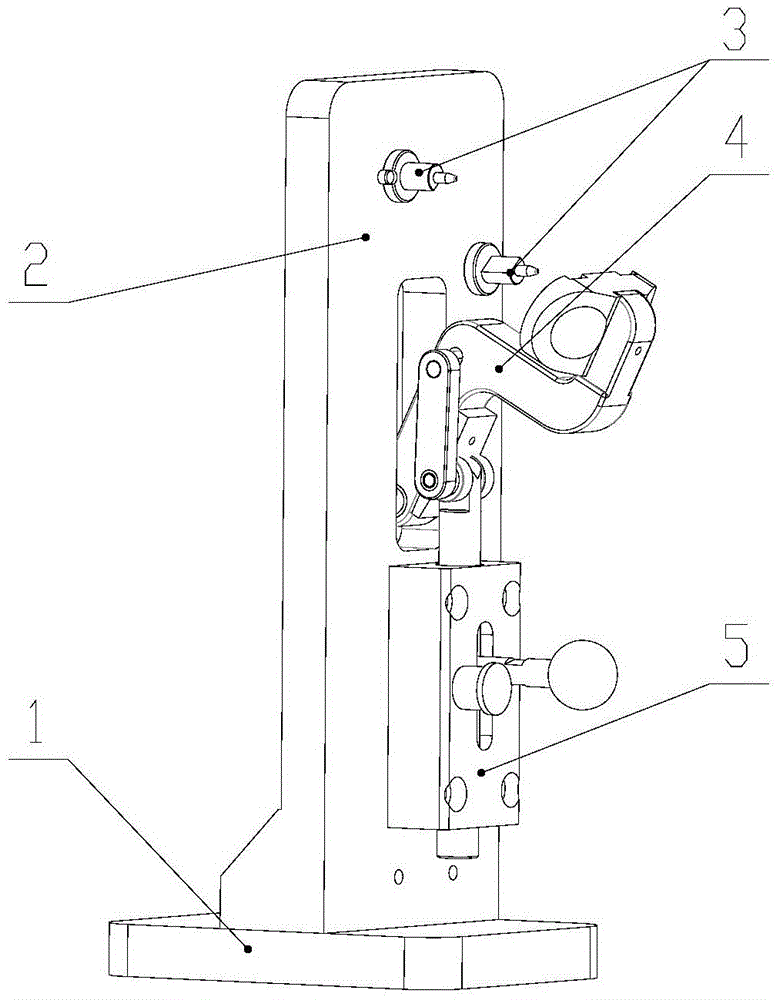
[0038] see Figure 1-4 , The present invention is a fixture with self-locking function, which includes: fixture base 1, fixture vertical plate 2, workpiece positioning pin 3, pressing assembly 4 and guide assembly 5.

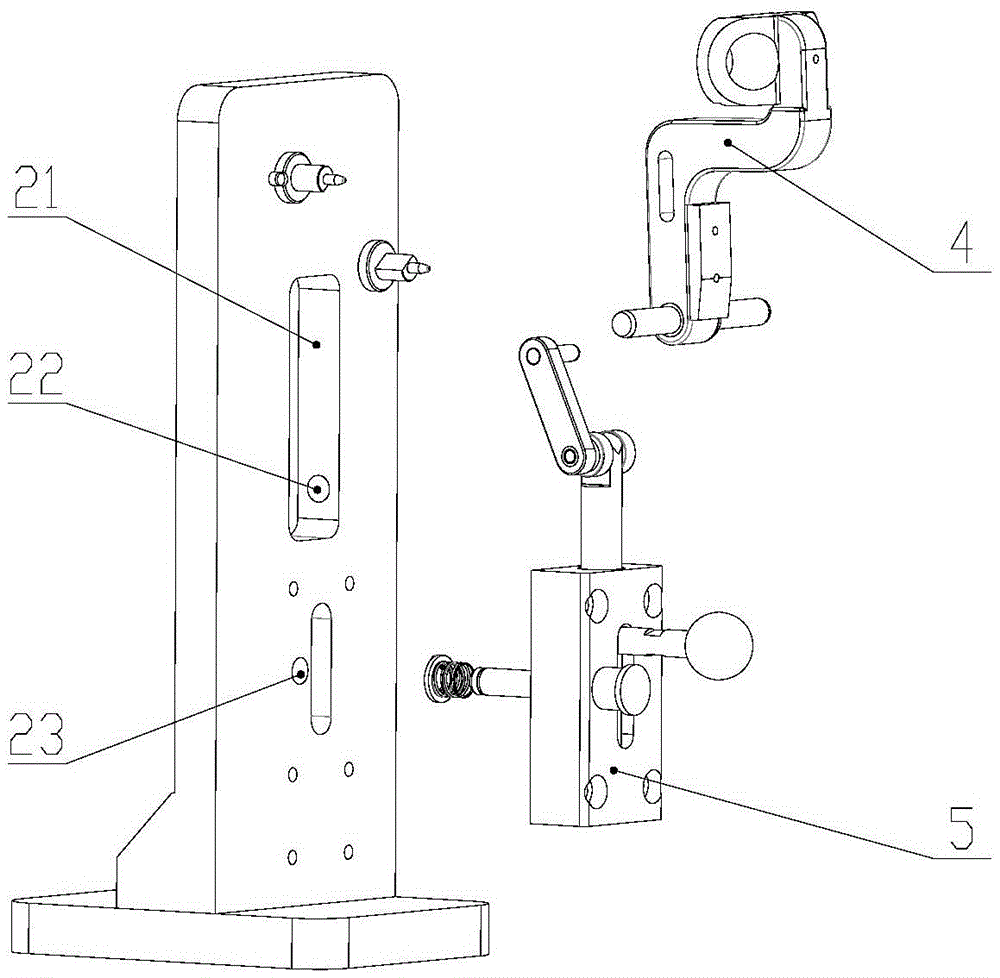
[0039] The clamp vertical plate 2 is vertically fixedly connected to the top surface of the clamp frame 1 by bolts, and the front side of the clamp vertical plate 2 is provided with a vertically extending relief groove 21 and a lock located obliquely below the relief groove 21. Rod passing holes 23 , wherein, rotation pin installation holes 22 are symmetrically opened on the opposite left and right sides of the relief groove 21 .

[0040] The workpiece positioning pins 3 are used to locate the workpiece to be clamped, and the number is at least two. These workpiece positioning pins 3 are arranged on the front side of the fixture ver...


PUM


Abstract

The invention relates to a clamp with a self-locking function. The clamp comprises a clamp machine base, a clamp vertical plate, workpiece positioning pins, a pressing assembly and a guide assembly, wherein the clamp vertical plate is vertically connected with the top face of the clamp machine base, the front side face of the clamp vertical plate is provided with a receding groove extending vertically and a lock rod passing hole below the receding groove, the workpiece positioning pins are fixedly connected with the front side face of the clamp vertical plate and located above the receding groove, the pressing assembly is rotatably connected with the receding groove and used for pressing a workpiece, and the left side face of the pressing assembly is provided with a sliding groove extending vertically. A handle connection rod in the guide assembly moves upwards to drive the pressing assembly to rotate, so that the pressing assembly clamps the workpiece between the pressing assembly and the clamp vertical plate; by means of a lock rod in the guide assembly, a vertical connection rod is automatically locked under the action of a lock rod spring after the pressing assembly presses the workpiece, and according the workpiece is clamped reliably.

Description

technical field [0001] The invention relates to a clamp, in particular to a clamp with a self-locking function. Background technique [0002] In the automatic assembly process of the product, the workpiece is generally clamped on the accompanying fixture, so that the workpiece moves to each station with the fixture, and finally the assembly is completed by the equipment. Therefore, in the assembly process, it is necessary to ensure that the workpiece is reliably clamped in the pallet. For this reason, relevant manual, electric and pneumatic clamps have been developed in the prior art. However, since this type of clamp needs to be equipped with an independent drive mechanism, that is to say, the drive mechanism and the clamping mechanism of the workpiece are not organically integrated, so This type of fixture is generally complex in structure, large in size and heavy in weight, which is not conducive to the lightweight of the tooling fixture, and once there is a problem with...

Claims


Application Information

Patent Timeline
Patent Type & Authority Patents(China)
IPC IPC(8): B25B11/02
CPCB25B11/02
Inventor 居淑芬黄曼顾卓超刘德俊张海洪
Owner SHANGHAI KELAI MECHATRONICS ENG CO LTD
Why Eureka
Try Eureka