Supercharge Your Innovation With Domain-Expert AI Agents!

Carton binding machine

A technology of binding machine and carton, applied in the field of carton binding machine, can solve the problems of narrow support arm, low work efficiency, laborious operation of workers, etc. of the binding machine, and achieve the effect of fast binding speed and compact structure

Inactive Publication Date: 2014-08-06
安徽蚌埠市三和纸箱机械有限公司
View PDF7 Cites 1 Cited by
  • Summary
  • Abstract
  • Description
  • Claims
  • Application Information

AI Technical Summary

Problems solved by technology

The support arm of the current binding machine is relatively narrow. When binding the cartons, it is necessary to rely on manual holding of the cartons for positioning. The positioning accuracy is greatly affected by human beings, and the quality is difficult to unify. Moreover, the workers are laborious to operate and the work efficiency is low.

Method used


Image

  • Carton binding machine
  • Carton binding machine

Examples


Embodiment Construction

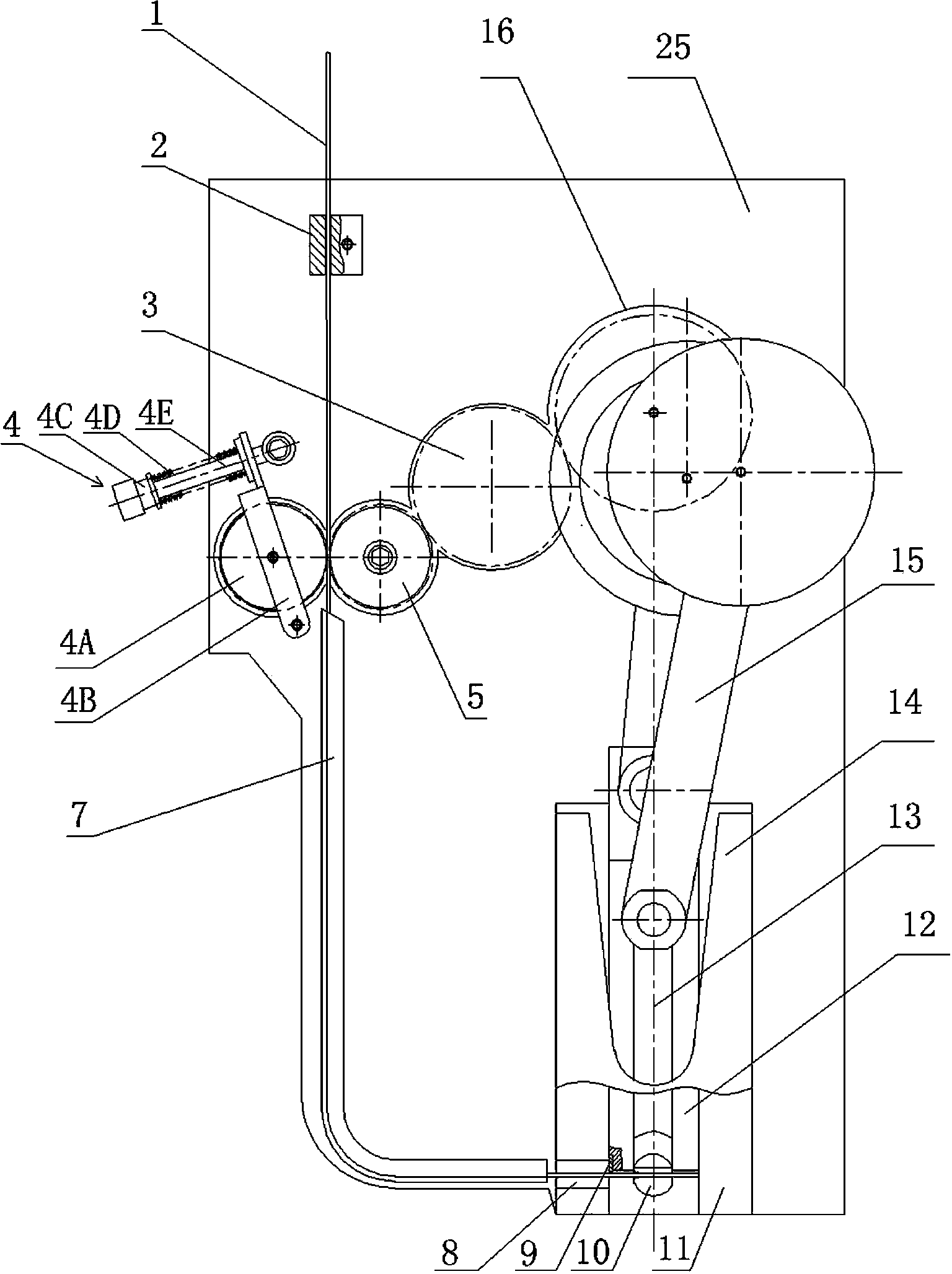
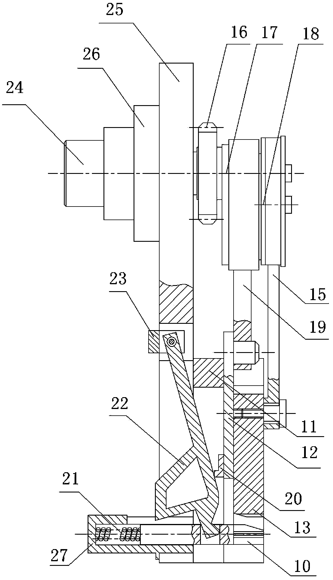
[0023] Such as figure 1 and figure 2 As shown, a carton binding machine provided by the present invention is composed of the following components:

[0024] 1. Frame and spindle assembly

[0025] Such as figure 1 and figure 2 As shown, the frame and main shaft assembly includes a frame 25, and the frame 25 is provided with a main shaft hole, a spring plate groove, a sleeve hole, a springboard groove and several threaded holes. The frame 25 is connected with a bearing seat 26 , and the bearing seat 26 is connected with a main shaft 24 .

[0026] 2. Wire feeding components

[0027] Such as figure 1 As shown, the wire feeding assembly consists of a wire feeding slider 2, a wire feeding wheel 5, and a wire pressing device 4

[0028] , 7 components of wire guide rails.

[0029] The wire feeding slider 2 is connected with the frame 25, and the wire feeding slider 2 is provided with a square through hole.

[0030] The wire feed roller 5 is connected with the above-mentioned...


PUM


Abstract

The invention relates to a carton binding machine. The carton binding machine comprises the following components of (a) a machine frame (25) and a main shaft (24), (b) a feed assembly formed by a feed sliding block (2), a feed wheel (5), a paper pressing device (4) and a paper conveying guide rail (7), (c) a punch assembly formed by a sliding chute (11), a feed block (8), an outer punch (12) and an inner punch (13), (d) a take-up spring assembly formed by a sleeve (27), a tongue (10) and a take-up plate (22) and (e) a cam assembly formed by an inner cam (17) and an outer cam (18). The carton binding machine has the advantages of being compact in structure, free from being stuck by nails and high in binding speed.

Description

technical field [0001] The invention relates to a packaging machine, in particular to a carton binding machine. Background technique [0002] The processing methods of cartons mainly include three categories: nailing, gluing and folding. At present, the most widely used in conventional carton forming is nailing. The carton binding machine is the key to the processing of nailing. equipment. Carton binding machines are mostly foot-operated nail box machines, and their structure is mainly composed of nailing device, working arm, supporting arm, driving motor, transmission clutch, body and foot switch. When working, the motor is driven. When the nail box is needed, the cardboard is manually supported, and the foot switch is pressed to turn on the nail head action, and the nail head is cycled; when the foot switch is not stepped on, the transmission clutch does not operate, and the nail head does not nail. The support arm of the current binding machine is relatively narrow. Whe...

Claims


Application Information

Patent Timeline
IPC IPC(8): B31B1/68B31B50/68
Inventor 年福东
Owner 安徽蚌埠市三和纸箱机械有限公司
Features
  • R&D
  • Intellectual Property
  • Life Sciences
  • Materials
  • Tech Scout
  • Unparalleled Data Quality
  • Higher Quality Content
  • 60% Fewer Hallucinations
Learn More