Deceleration rate control-based antiskid braking system and method for airplane

A technology of anti-skid braking and deceleration rate, applied in the direction of aircraft braking arrangement, brake, control mechanism, etc., can solve the problems of stepless adjustment of deceleration rate, unstable deceleration process of aircraft, affecting aircraft safety, etc. Effect

Inactive Publication Date: 2014-08-06
XIAN AIRCRAFT DESIGN INST OF AVIATION IND OF CHINA
View PDF5 Cites 20 Cited by
  • Summary
  • Abstract
  • Description
  • Claims
  • Application Information

AI Technical Summary

Problems solved by technology

[0002] Aircraft brake control system is an important airborne equipment. Whether the brake system can work normally will seriously affect the safety of the aircraft. At the same time, during the braking process of the aircraft, the stability of the anti-skid brake system will directly affect the stability of the aircraft and the passenger ride. At present, the normal braking process of the aircraft is usually controlled based on the brake pressure. When the braking pressure is too high, the aircraft is in the process of frequent skidding. At this time, the deceleration process of the aircraft is extremely unstable, and the deceleration rate of the aircraft is in a large fluctuation range. In today's more advanced civil aircraft, there is usually an automatic braking system, and the automatic braking control is controlled by the deceleration rate. When the aircraft uses automatic braking, it usually works after a certain level is selected. When the pilot feels that the selected deceleration rate level is not appropriate, it will switch to normal braking with pedals.
Therefore, it cannot achieve stepless adjustment to the deceleration rate during the braking process.

Method used


Image

  • Deceleration rate control-based antiskid braking system and method for airplane
  • Deceleration rate control-based antiskid braking system and method for airplane

Examples


Embodiment Construction

[0014] The present invention will be described in detail below in conjunction with the accompanying drawings.

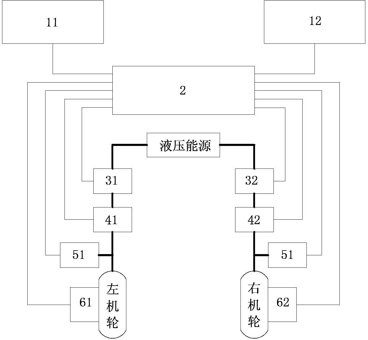
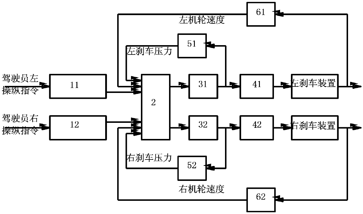
[0015] Such as figure 1 As shown, an aircraft anti-skid braking system based on deceleration rate control includes a left brake command sensor 11, a right brake command sensor 12, an anti-skid brake controller 2, a left electromagnetic hydraulic lock 31, a right magnetic hydraulic lock 32, and a left brake control valve. 41, right brake control valve 42, left brake pressure sensor 51, right brake pressure sensor 52, left machine wheel speed sensor 61, right machine wheel speed sensor 62; Device 2 is electrically connected, the left electromagnetic hydraulic lock 31 outlet is connected with the left brake control valve 41; the right electromagnetic hydraulic lock 32 outlet is connected with the right brake control valve 42; the left brake control valve 41 is connected with the left wheel brake device, and the right brake control valve 42 is connected with The right w...


PUM


Abstract

The invention relates to a deceleration rate control-based antiskid braking system and a deceleration rate control-based antiskid braking method for an airplane. The system comprises a left braking instruction sensor, a right braking instruction sensor, an antiskid braking controller, electromagnetic hydraulic locks, braking control valves, braking pressure sensors and airplane wheel speed sensors. A set of hydraulic source is used for providing pressure, and enters the two electromagnetic hydraulic locks respectively, one braking control valve is connected behind each electromagnetic hydraulic lock, one pressure sensor is connected behind each braking control valve, left and right braking airplane wheels are connected behind the pressure sensors, the airplane wheel speed sensors are mounted in wheel shafts of the airplane wheels, signals of the braking instruction sensors, the pressure sensors and the airplane wheel speed sensors enter the antiskid braking controller, and the braking controller controls the electromagnetic hydraulic locks and the braking control valves. According to the system and the method, the airplane is stably decelerated in a braking process, the deceleration rate can be steplessly regulated, and the braking deceleration stability of the airplane and the comfort of a driver and passengers are improved.

Description

technical field [0001] The invention relates to an aircraft antiskid braking system and method based on deceleration rate control. Background technique [0002] Aircraft brake control system is an important airborne equipment. Whether the brake system can work normally will seriously affect the safety of the aircraft. At the same time, during the braking process of the aircraft, the stability of the anti-skid brake system will directly affect the stability of the aircraft and the passenger ride. At present, the normal braking process of the aircraft is usually controlled based on the brake pressure. When the braking pressure is too high, the aircraft is in the process of frequent skidding. At this time, the deceleration process of the aircraft is extremely unstable, and the deceleration rate of the aircraft is in a large fluctuation range. In today's more advanced civil aircraft, there is usually an automatic braking system, and the automatic braking control is controlled by...

Claims


Application Information

Patent Timeline
Patent Type & Authority Applications(China)
IPC IPC(8): B60T8/32B64C25/44
Inventor 刘泽华谢彦秦成
Owner XIAN AIRCRAFT DESIGN INST OF AVIATION IND OF CHINA
Why Eureka
Try Eureka