A kind of line friction U-shaped belt conveyor
What is Al technical title?
Al technical title is built by PatSnap Al team. It summarizes the technical point description of the patent document.
A belt conveyor, U-shaped technology, used in conveyors, conveyor objects, transportation and packaging, etc., can solve problems such as low conveying efficiency, huge energy consumption, environmental pollution, etc., to improve utilization efficiency and ensure normal operation. , the effect of avoiding pollution
Active Publication Date: 2017-02-22
QINGDAO HUAXIA RUBBER IND
View PDF6 Cites 0 Cited by
Summary
Abstract
Description
Claims
Application Information
AI Technical Summary
This helps you quickly interpret patents by identifying the three key elements:
Problems solved by technology
Method used
Benefits of technology
Problems solved by technology
In order to achieve the purpose of large transportation, it is necessary to increase the power unit in sections to realize the transportation. The transportation efficiency is very low, the energy consumption is very huge, and the items conveyed in the U-shaped groove are easy to slip from the belt to waste resources and pollute the environment.
Method used
Image
Click on the blue label to locate the original text in one second.
Reading with bidirectional positioning of images and text.
Examples
Embodiment 1
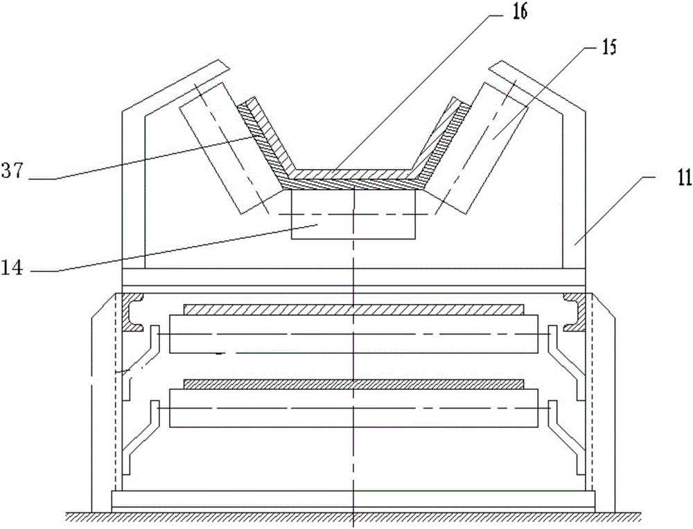
[0023] Such as Figure 1 to Figure 4 As shown, the present invention includes a main engine and at least one auxiliary force-applying device installed on the main engine. The main engine includes a bracket, and is installed on the bracket: the head roller 12 positioned at the end of the bracket, the tail roller positioned at the other end of the bracket 13. Loading idler 14, edge idler 15, drive belt 16 connecting the head roller 12 and tail roller 13 and located on the surface of the load idler 14 and edge idler 15, the head roller 12 is externally connected with a power device The auxiliary booster device is located between the drive belts 16, including: secondary traction rollers 21, secondary driven rollers 22, booster rollers 24, connecting secondary traction rollers 21 and secondary driven rollers 22 installed on the main frame , the booster belt 23 located on the booster roller 24 and in contact with the drive belt 16, the auxiliary traction roller 21 is externally conn...
PUM
Abstract
The invention relates to a linear friction U-type belt conveyor which comprises a main machine and at least one auxiliary forcing device installed on the main machine. The main machine comprises a support, a head idler wheel, a tail idler wheel, a carrying carrier roller, a flange carrier roller and driving belts, wherein the head idler wheel, the tail idler wheel, the carrying carrier roller, the flange carrier roller and the driving belts are installed on the support, the head idler wheel is located at one end of the support, the tail idler wheel is located at the other end of the support, and the head idler wheel and the tail idler wheel are connected through the driving belts which are located on the surfaces of the carrying carrier roller and the flange carrier roller. The auxiliary forcing device is located between the driving belts, and comprises an auxiliary traction idler wheel, an auxiliary driven idler wheel, a forcing fixed platform and forcing belts, wherein the auxiliary traction idler wheel, the auxiliary driven idler wheel, the forcing fixed platform and the forcing belts are installed on the support of the main machine, and the auxiliary traction idler wheel and the auxiliary driven idler wheel are connected through the forcing belts which are located on the forcing fixed platform and are in contact with the driving belts. The linear friction U-type belt conveyor is characterized in that the grooving angle between the carrying carrier roller and the flange carrier roller ranges from 60 degrees to 90 degrees, each driving belt comprises an upper covering layer, a lower covering layer, an upper bonding layer, a lower bonding layer and a framework layer, the upper bonding layer and the lower bonding layer are connected with the upper covering layer and the lower covering layer respectively, and the framework layer is located between the upper bonding layer and the lower bonding layer and provided with a plurality of steel wire ropes.
Description
technical field [0001] The invention belongs to the field of transportation, and in particular relates to a line friction U-shaped belt conveyor. Background technique [0002] With the development of society and economy, related industries have higher and higher requirements for conveyors. Small belt conveyors have been difficult to meet the transportation needs. Large-capacity, long-distance belt conveyors have become the development trend of the industry. It is precisely because of the increase in the conveying volume and the lengthening of the distance that the power requirements of the conveyor driving device have also increased correspondingly, and even the method of segmented transportation has to be adopted, which not only reduces the transportation efficiency, but also easily causes the transported goods to slip and waste. resources while polluting the environment, U-shaped belt conveyor came into being. However, limited by the conventional conveyor belt manufacturi...
Claims
Application Information
Patent Timeline
Application Date:The date an application was filed.
Publication Date:The date a patent or application was officially published.
First Publication Date:The earliest publication date of a patent with the same application number.
Issue Date:Publication date of the patent grant document.
PCT Entry Date:The Entry date of PCT National Phase.
Estimated Expiry Date:The statutory expiry date of a patent right according to the Patent Law, and it is the longest term of protection that the patent right can achieve without the termination of the patent right due to other reasons(Term extension factor has been taken into account ).
Invalid Date:Actual expiry date is based on effective date or publication date of legal transaction data of invalid patent.