

Regulating mechanism for stably regulating tension of carrier roller belt
A technology for adjusting the mechanism and tension force, which is applied in the direction of conveyors, transportation and packaging, etc., can solve the problems of decreased transmission efficiency, unstable center of gravity of belt materials, and low belt transmission efficiency, so as to improve transmission efficiency and work stability , to avoid the effect of reducing the transmission efficiency
- Summary
- Abstract
- Description
- Claims
- Application Information
AI Technical Summary
Problems solved by technology
Method used
Image

Examples
Embodiment 1
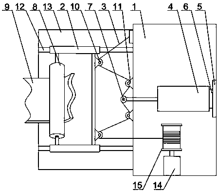
[0021] Such as figure 1 As shown, a belt 9 tension adjustment structure of the present invention includes an adjustment platform 1, a traction line 3, a support frame 13 and a fence body 2, the adjustment platform 1 is connected to the fence body 2, and the belt 9 bypasses the fence body 2, so The adjustment platform 1 is connected to the fence body 2 through a pulley block, a connecting rod 12 is arranged on the support frame 13, and the fence body 2 is slidably arranged on the connecting rod 12, and a cylinder 4 connected to each other is arranged on the adjustment platform 1 And the baffle plate 5, a pressure sensor 6 is installed between the tail end of the cylinder 4 and the baffle plate 5, and the pressure sensor 6 is connected with the driving device of the cylinder 4 through a wire, the traction line 3 bypasses the pulley block, and the traction line 3 The two ends of the two sides are respectively fixed on the adjustment platform 1, and a roller 7 is installed on the ...
Embodiment 2
[0023] Such as figure 1 As shown, on the basis of Embodiment 1, the present embodiment includes two first pulleys 10 and two second pulleys 11, and the two first pulleys 10 are installed on the fence body 2 close to the adjustment platform 1- On the side, a plurality of second pulleys 11 are arranged symmetrically on both sides of the roller 7 with the axis of the cylinder as an axis, and the first pulley 10 is connected with the second pulley 11 and the roller 7 through the traction line 3 . The two first pulleys 10 are respectively placed on the sides of the fence body 2, the second pulleys 11 are located on both sides of the roller 7, and the roller 7 moves to the direction of the belt 9, and the two first pulleys 10 are driven by the traction line 3 Start to move towards the direction of the adjustment platform 1, and realize the slow and precise adjustment of the belt 9. When the roller 7 moves to a certain distance, the pressure sensor 6 between the cylinder 4 and the ba...
Embodiment 3
[0025] Such as figure 1 As shown, on the basis of Embodiment 1, the present embodiment includes a motor 14 and a reel 15, the output end of the motor 14 is connected to the reel 15, and the end of the pulling wire 3 is connected to the reel 15 . When the head and the end of the traction line 3 are respectively fixed to the adjustment platform 1, the traction line 3 will loosen during a long period of work, which will further increase the distance between the cylinder 4 and increase the difficulty of adjusting the tension of the belt 9. The end of the traction line 3 is connected to the reel 15, and the reel 15 will recover the traction line 3 under the drive of the motor 14 within a fixed period of time, and carry out certain regulation on the traction line 3 to ensure that the fence body will 2 Stability of movement.
PUM
 Abstract
Description
Claims
Application Information