Check patentability & draft patents in minutes with Patsnap Eureka AI!
Automatic feeding material rack
What is Al technical title?
Al technical title is built by PatSnap Al team. It summarizes the technical point description of the patent document.
A technology of automatic feeding and material racking, applied in the field of material racking, can solve the problems of increasing production input costs, unreachable, low production efficiency, etc., and achieve the effect of improving machine working efficiency, maintaining normal operation, and accurately feeding and loading materials
Active Publication Date: 2016-05-25
星光印刷(苏州)有限公司
View PDF7 Cites 2 Cited by
Summary
Abstract
Description
Claims
Application Information
AI Technical Summary
This helps you quickly interpret patents by identifying the three key elements:
Problems solved by technology
Method used
Benefits of technology
Problems solved by technology
However, the main functions of the existing various types of material racks in various manufacturing enterprises are still limited to loading, transshipment, packaging and transportation
The loading of raw materials in the production process is still manually operated and executed on a single piece; manual single-piece loading cannot guarantee the uninterrupted production of the equipment, the production efficiency is low, and the market demand cannot be met. The manual labor intensity is high and the high efficiency of automation cannot be guaranteed. production, thereby increasing production input costs
Especially for paper product processing enterprises, it is not easy to guarantee the feeding and clamping of raw materials, and the quality of manual feeding and processed products is uneven, which cannot reach a unified standard; The problem of material and positioning and clamping is a topic that needs to be solved urgently in the industry
Method used
Image
Click on the blue label to locate the original text in one second.
Reading with bidirectional positioning of images and text.
Examples
Embodiment Construction
[0025] Below in conjunction with accompanying drawing and specific embodiment, further illustrate the present invention, should be understood that these embodiments are only for illustrating the present invention and are not intended to limit the scope of the present invention, after having read the present invention, those skilled in the art will understand various aspects of the present invention Modifications in equivalent forms all fall within the scope defined by the appended claims of this application.
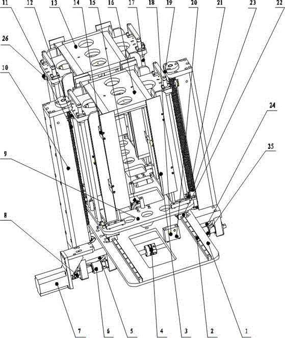
[0026] as attached figure 1 An automatic feeding material rack is shown, including a support structure, a feeding control system, and a material placement mechanism;
[0027] The support structure includes: a support base plate 1, a screw support frame 10, the screw support frame 10 is vertically fixed to the support base plate 1, and a guide rail 2 is installed on the support base plate 1;
[0028] Described material placement mechanism comprises: bearing plate 9, the ...
PUM
Abstract
The invention provides an automatic feeding material frame which comprises a supporting bottom plate, a screw rod supporting frame, a bearing plate, a material positioning connecting plate, a first material bottom plate, a second material bottom plate, guide columns, a servo motor, worms, worm gears, screw rods and nut pairs. The screw rod supporting frame is used for fixing the screw rods in the axis direction and is perpendicular to the supporting bottom plate, and the screw rods are arranged on the inner sides of two arms of the supporting frame respectively. A station converting cylinder is arranged on the lower portion of the bearing plate, and the guide columns are arranged on the left side and the right side of the first material bottom plate and the left side and the right side of the second material bottom plate and are respectively and fixedly connected with the bearing plate. The first material bottom plate, the second material bottom plate and half nuts are connected to be used as the nut pairs and can move up and down along the guide columns. The shaft heads of the screw rods are connected with the worm gears, and the servo motor is arranged on the lower portion of the supporting bottom plate and is connected with the worms through couplers. According to the automatic feeding material frame, the screw rods are controlled to rotate through transmission of the servo motor, the worm gears and the worms, the corresponding nut pairs gradually ascend or descend along with rotating of the screw rods, automatic and precise feeding can be achieved, two material bottom plates are provided, when materials on one bottom plate are run out, the second bottom plate is used for supplementing materials quickly, continuous material feeding is achieved, and the production efficiency is improved.
Description
technical field [0001] The invention relates to an automatic control device, in particular to a material rack for uninterrupted feeding and automatic and precise feeding of raw materials for paper products. Background technique [0002] At present, manufacturing, as a pillar industry of my country's national economy, is the leading sector of my country's economic growth and the foundation of economic transformation; as an important support for economic and social development, manufacturing is the main channel for urban employment in my country and a concentrated expression of international competitiveness. Manufacturing refers to the transformation of manufacturing resources (materials, energy, equipment, tools, funds, technology, information and manpower, etc.) Consumer Products Industry. As a necessary station equipment for loading and transporting raw materials and finished products, the material rack plays a very important role in the production, packaging and transport...
Claims
Application Information
Patent Timeline
Application Date:The date an application was filed.
Publication Date:The date a patent or application was officially published.
First Publication Date:The earliest publication date of a patent with the same application number.
Issue Date:Publication date of the patent grant document.
PCT Entry Date:The Entry date of PCT National Phase.
Estimated Expiry Date:The statutory expiry date of a patent right according to the Patent Law, and it is the longest term of protection that the patent right can achieve without the termination of the patent right due to other reasons(Term extension factor has been taken into account ).
Invalid Date:Actual expiry date is based on effective date or publication date of legal transaction data of invalid patent.
