
A casting cleaning line self-transfer system

A casting cleaning and casting technology, applied in foundry, casting equipment, conveyor objects, etc., can solve problems affecting work efficiency, wear, and large vehicles, and achieve the effect of improving production efficiency and high degree of automation

Active Publication Date: 2016-05-25
JIANGSU HENGLI HYDRAULIC
View PDF4 Cites 0 Cited by
  • Summary
  • Abstract
  • Description
  • Claims
  • Application Information

AI Technical Summary

Problems solved by technology

[0002] In actual production, the transportation between the shot blasting machine and the grinding machine during the casting cleaning process is transferred by special vehicles. This will consume a lot of vehicles and put forward higher requirements for the space of the workshop. , and will also increase the safety hazards to the workers in the workshop
Even if there is no vehicle for transportation, there is a rail transfer line, and the rail transfer vehicle is powered by a cable when it is transported. When the rail transfer vehicle moves, there is a long cable behind it. The cable rubs on the ground, which is prone to wear and tear problems; workers, vehicles Traveling needs to cross the cable, which will definitely bring safety hazards
The existing multi-track transfer vehicle has a small number of transfers at one time, and it cannot realize multiple transportation in one cycle. The grinding machine will have no material processing, which will affect the work efficiency; and the start, transportation, and stop of the rail transfer vehicle need to rely on manual control, requiring multiple parties. Cooperate, increase labor cost, low production efficiency

Method used


Image

  • A casting cleaning line self-transfer system
  • A casting cleaning line self-transfer system
  • A casting cleaning line self-transfer system

Examples


Embodiment 1)

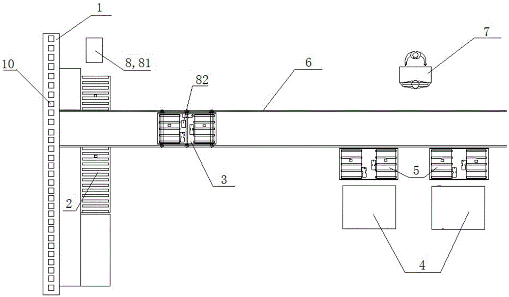
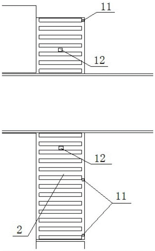
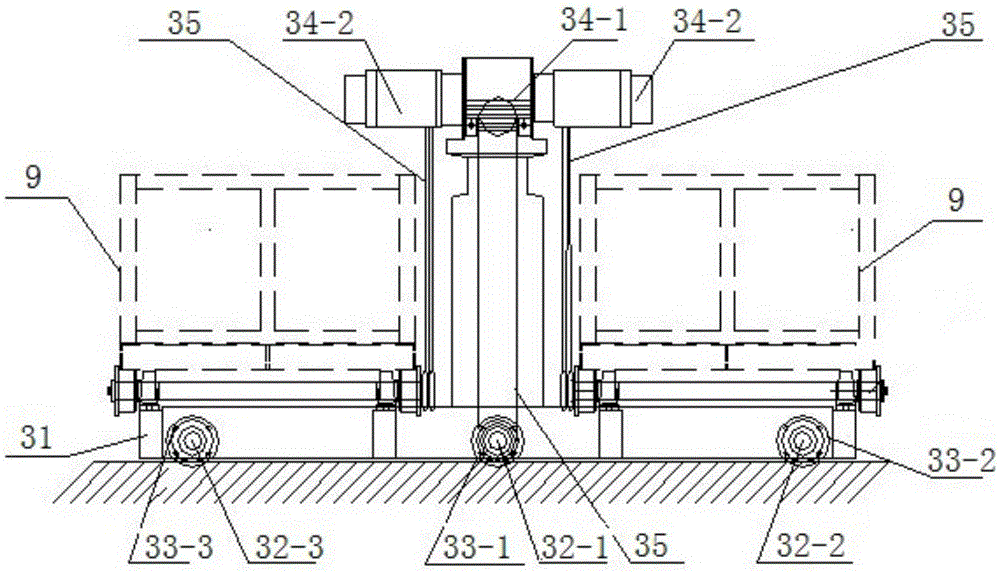
[0024] See Figure 1 to Figure 6 , the self-transfer system of the casting cleaning line of the present invention includes a shot blasting casting transportation line 1, a shot blasting machine rear roller table 2 arranged in parallel with the shot blasting casting transportation line 1, and a shot blasting casting transportation line 1 and a shot blasting casting rear roller table 2 The vertically arranged track 6 and the grinder 4 located on the outside of the end of the track 6 away from the rear roller table 2 of the shot blasting casting. There is also a front roller track 5 between the grinder 4 and the track 6; the upper part of the track 6 is provided with a track transfer The car 3 and the other side of the track 6 are also equipped with a main control console 7. When the automatic control system fails or is otherwise necessary, the transfer of the casting cleaning line can be realized through manual control of the self-transfer system, thereby ensuring the cleaning an...


PUM


Abstract

The invention relates to a casting cleaning line self-transferring system which sequentially comprises a shot blasting casting transferring line, a shot blast machine rear roller bed parallel with the shot blasting casting transferring line, a rail vertical to the shot blasting casting transferring line and the shot blast machine rear roller bed and a polisher located on the outer side of one end, away from the shot blast machine rear roller bed, of the rail. A polisher front roller bed is further disposed between the polisher and the rail. A rail transferring vehicle is disposed on the upper portion of the rail. A master control panel is disposed on the other side of the rail. The casting cleaning line self-transferring system has the advantages that the whole transferring is completed through the system, high automation level is achieved, a large amount of transferring vehicles is not needed, the system is convenient, fast and safe, the problem that the existing rail transferring systems rely on cables for power transmission is solved, and manual and automatic control of the transferring system are achieved; each of shot blasting machine rear roller bed, the rail transferring vehicle and the polisher front roller bed adopts one body two positions, continuous feed of the polisher can be achieved, and production efficiency is increased greatly.

Description

technical field [0001] The invention relates to a workpiece cleaning device for a casting production line, in particular to an automatic transfer system for a casting cleaning line. Background technique [0002] In actual production, the transportation between the shot blasting machine and the grinding machine during the casting cleaning process is transferred by special vehicles. This will consume a lot of vehicles and put forward higher requirements for the space of the workshop. , and will also increase the safety hazards to the workers in the workshop. Even if there is no vehicle for transportation, there is a rail transfer line, and the rail transfer vehicle is powered by a cable when it is transported. When the rail transfer vehicle moves, there is a long cable behind it. The cable rubs on the ground, which is prone to wear and tear problems; workers, vehicles Traveling needs to cross the cable, which will inevitably bring safety hazards. The existing multi-track tra...

Claims


Application Information

Patent Timeline
Patent Type & Authority Patents(China)
IPC IPC(8): B65G35/00B65G43/00B24B41/00B22D47/00B22D31/00
Inventor 汪立平孙斐胡静庄晔邱永宁缪小吉
Owner JIANGSU HENGLI HYDRAULIC
Learn More