Special-shaped GRG block partition limiting installation structure and splicing method thereof

A technology of installation structure and splicing method, which is applied in building structure, covering/lining, construction, etc., can solve the problems such as difficult to control the installation quality of special-shaped GRG, and achieve the effect of ensuring the overall installation effect

Active Publication Date: 2014-08-06
GOLD MANTIS CONSTR DECORATION
View PDF5 Cites 7 Cited by
  • Summary
  • Abstract
  • Description
  • Claims
  • Application Information

AI Technical Summary

Problems solved by technology

[0006] The purpose of the present invention is to provide a special-shaped plate GRG block partition limit installation structure, which can solve the problem that the installation quality of large-area special-shaped GRG is difficult to control, and provide an efficient and controllable installation solution

Method used


Image

  • Special-shaped GRG block partition limiting installation structure and splicing method thereof
  • Special-shaped GRG block partition limiting installation structure and splicing method thereof
  • Special-shaped GRG block partition limiting installation structure and splicing method thereof

Examples


Embodiment 1

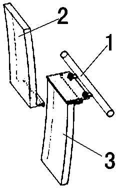
[0035] Embodiment one: if Figure 8 Shown: a special-shaped plate GRG block partition limit installation structure, which includes a fixed steel frame 1, an upper GRG plate 2, and a lower GRG plate 3. The upper GRG plate 2 is provided with an "L" shaped flange at the junction of the lower GRG plate 3 . The lower GRG plate 3 is provided with an "L"-shaped flange at the junction of the upper GRG plate 2, and the upper GRG plate 2 reserves an L-shaped flange on the GRG plate 3.

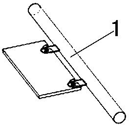
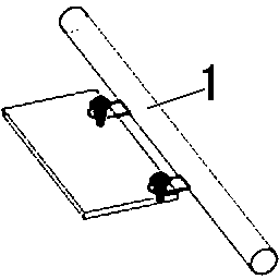
[0036] Such as Figure 1 to Figure 4 As shown, the fixed steel frame 1 is fixed to the GRG inner steel frame structure, and the upper GRG plate 2 and the lower GRG plate 3 are joined together to form a structural unit; the L-shaped flange of the lower GRG plate 3 and the L-shaped flange of the upper GRG plate 2 Form a "U" shaped groove.

[0037] Such as Figure 6 As shown, the back of the lower GRG plate 3 where the upper GRG plate 2 meets is reinforced with a GRG “U”-shaped plate 5 .

[0038] Such ...

Embodiment 2

[0040] Embodiment two: if Figure 1 to Figure 5 As shown, the splicing method of the special-shaped plate GRG block partition limit installation structure includes the following steps,

[0041] A. According to the division of the GRG typesetting area, do the overall laying-out of the site, and set the zero-time fixed steel structure; install the limit woodworking board, fix it with bolts, and fix it on the fixed steel frame 1 through the U-shaped opening on the limit woodworking board and the bolts Limiting woodworking board: the limiting woodworking board is left to fix the U-shaped opening and fixed on the fixed steel frame 1 by bolts.

[0042] B. Put the upper thread on the limiting woodworking board, and install the GRG plates on both sides according to the completed upper thread: the upper GRG plate 2 and the GRG plate 3 are installed and fixed by splicing the L-shaped flange and the limiting woodworking board to support the limit: The limit woodworking board is located ...


PUM


Abstract

The invention discloses a special-shaped GRG block partition limiting installation structure. The special-shaped GRG block partition limiting installation structure comprises a fixing steel frame (1), upper GRG plates (2) and lower GRG plates (3). The upper GRG plates (2) and the lower GRG plates (3) are mutually and correspondingly spliced to form structural units; the structural units are installed side by side, the back face of each structural unit is fixed to the fixing steel frame (1), and the fixing steel frame (1) is installed on an inner steel frame structure. The invention further discloses a splicing method of the special-shaped GRG block partition limiting installation structure. According to the special-shaped GRG block partition limiting installation structure and the splicing method of the special-shaped GRG block partition limiting installation structure, the problem that installation quality of large-area special-shaped GRG is difficult to control is solved, the quality problems such as installation errors and dislocation are solved, and the overall installation effect of the GRG is guaranteed.

Description

technical field [0001] The invention relates to a special-shaped plate GRG block partition limit installation structure and its splicing method. Background technique [0002] The traditional special-shaped GRG installation relies on the manufacturer's mold parting number, and the on-site line is gradually adjusted and installed. This technology has inevitable disadvantages: [0003] 1. Since it is difficult to accurately set out the installation position of each piece of GRG during the installation of large-area special-shaped GRG, a large amount of experience is relied on the construction personnel for installation, the construction progress is slow, and the installation deviation is large. [0004] 2. There is no way to pre-control the installation process of large-area special-shaped GRG in traditional technology. It can only control some basic points and cannot control the whole. Once deviations occur, rework will be time-consuming and labor-intensive. [0005] 3. The l...

Claims


Application Information

Patent Timeline
Patent Type & Authority Applications(China)
IPC IPC(8): E04F13/22
Inventor 徐金峰金一张伟毛绍刚刘建国汤泽中赵石军颜丙月李大军杨涛朱晖冯雯媛董凡朱银兵缪海荣王兵孙诗逸张传彪周丰昌
Owner GOLD MANTIS CONSTR DECORATION
Why Eureka
Try Eureka