Rotational flow shoe

A swirl shoe and swirl channel technology, applied in drilling equipment, drilling equipment and methods, earthwork drilling and other directions, can solve the problem of low pressure bearing capacity, easy to damage the suspended state of the floating shoe string, and it is difficult to ensure that the pipe string is centered and other problems to achieve the effect of reducing friction

Active Publication Date: 2014-08-06
CHINA PETROLEUM & CHEM CORP +1
View PDF5 Cites 2 Cited by
  • Summary
  • Abstract
  • Description
  • Claims
  • Application Information

AI Technical Summary

Problems solved by technology

However, the pressure bearing capacity of the floating shoe structure in the prior art is low, and the pressure in the well can easily damage the floating shoe so that the pipe string can no longer be in a suspended state, and it is difficult to ensure that the pipe string is centered in the wellbore

Method used


Image

  • Rotational flow shoe

Examples


Embodiment Construction

[0017] The present invention will be further described below in conjunction with accompanying drawing.

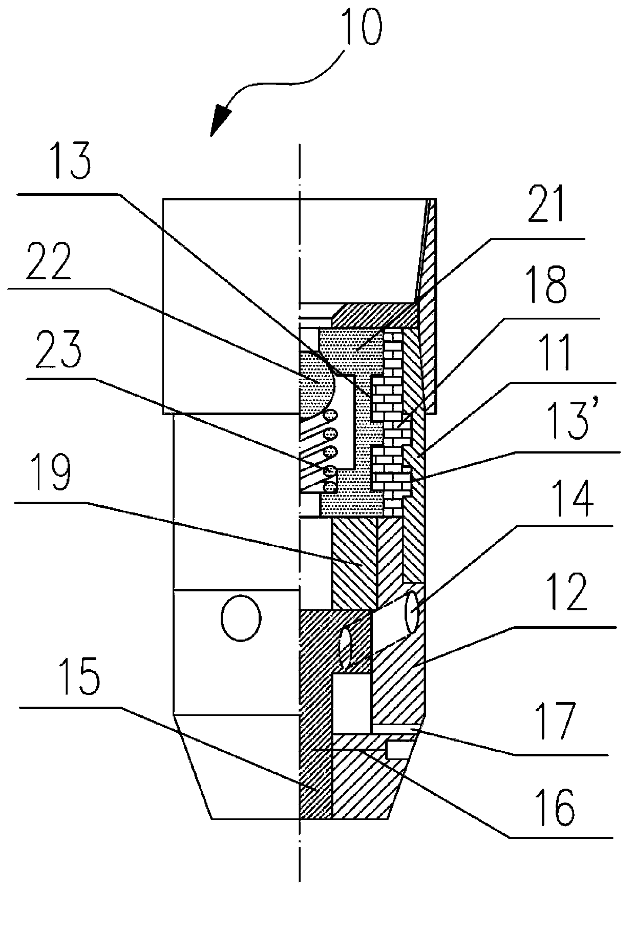
[0018] figure 1 The internal structure of the swirl shoe 10 according to the present invention is schematically shown. The swirl shoe 10 includes a casing 11, and a connecting pipe 12 is installed at the downstream end of the casing 11. Both the casing 11 and the connecting pipe 12 are hollow structures to form a fluid channel. In one embodiment, the connecting pipe 12 is also provided with a swirl channel 14 penetrating through the side wall of the connecting pipe 12, so as to establish circulation inside and outside the casing (not shown). In a preferred embodiment, the connecting pipe 12 is detachably connected to the downstream end of the casing 11, so that the assembly of the swirl shoe 10 is more convenient. In one embodiment, the connecting pipe 12 is screwed to the housing 11 .

[0019] The swirl shoe 10 also includes a differential pressure valve fixed inside th...


PUM


Abstract

The invention relates to a rotational flow shoe which comprises a hollow shell, a hollow connecting pipe is detachably mounted at the downstream end part of the shell to form a fluid passage, a rotational flow passage penetrating through the side wall of the connecting pipe is also formed in the connecting pipe, a differential pressure type valve capable of cutting off or communicating the fluid passage is fixedly arranged inside the shell, and a bearing slide block which can move in the axial direction and cover the rotational flow passage is arranged inside the connecting pipe and is connected with the connecting pipe through a cutting pin. The rotational flow shoe has the benefits that the pressure resistance is higher, and the rotational flow shoe is not affected by the cleanness of well fluid.

Description

technical field [0001] The invention relates to a cementing tool, in particular to a swirl shoe. Background technique [0002] With the advancement of oil drilling technology, in order to increase production, special wells such as high-inclination and extended-reach wells have increased year by year, but the cementing technology that matches the drilling technology has developed relatively slowly. Therefore, when the above-mentioned special well is completed, it is difficult to ensure the centering of the casing in the wellbore using conventional downhole tools. In addition, during the casing running process, the casing is subjected to relatively large frictional resistance, which makes casing running difficult, which directly affects the cementing quality. [0003] In order to solve these problems, floating collars and floating shoes are usually used in the prior art to achieve the centering of the casing in the wellbore. Its working principle is: during the casing runnin...

Claims


Application Information

Patent Timeline
Patent Type & Authority Applications(China)
IPC IPC(8): E21B7/20
Inventor 张明昌谭春勤郑晓志楚广川张然
Owner CHINA PETROLEUM & CHEM CORP
Why Eureka
Try Eureka