

Linear compressor
A linear compressor, fixed mechanism technology, applied in mechanical equipment, machines/engines, liquid variable capacity machinery, etc. Improve assembly flexibility, improve reliability, and ensure the effect of coaxiality
- Summary
- Abstract
- Description
- Claims
- Application Information
AI Technical Summary
Problems solved by technology
Method used
Image

Examples
Embodiment Construction
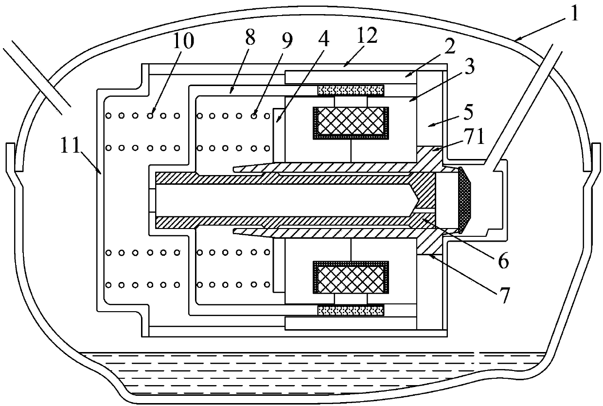
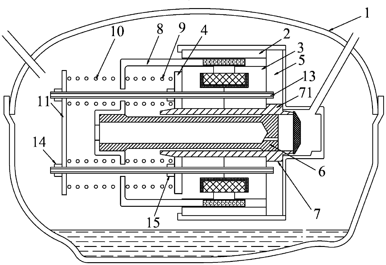
[0027] Refer below Figure 2~Figure 8 Shown is a detailed description of the specific implementation of the linear compressor of the present invention.
[0028] figure 2 and image 3 It is a structural schematic diagram of the linear compressor in the present invention, which is the first embodiment. Such as figure 2 and image 3 As shown, the cylinder 7 is a long-axis cylinder, that is, the axial length of the cylinder body of the cylinder 7 is greater than the axial length of the inner stator 3 . A flange 71 extending radially outward is formed on the outer peripheral surface of the cylinder 7 at the right end thereof, and the flange 5 is disposed on the outer peripheral surface of the flange 71 . The cylinder body of the air cylinder 7 protrudes into the inner stator 3 , and the outer peripheral surface of the cylinder body is in contact with the inner surface of the inner stator 3 . The right end surface of the inner stator 3 abuts against the left surface of the f...
PUM
 Abstract
Description
Claims
Application Information