Vacuum pressure regulating valve

A vacuum pressure and regulating valve technology, applied in valve details, safety valve, balance valve, etc., can solve the problems of complex structure and increased cost, and achieve the effects of reliable experimental performance, convenient pressure setting and energy saving.

Inactive Publication Date: 2014-08-06
AVIC SHENYANG AERODYNAMICS RES INST
View PDF6 Cites 1 Cited by
  • Summary
  • Abstract
  • Description
  • Claims
  • Application Information

AI Technical Summary

Problems solved by technology

If the suction capacity continues to increase, it is necessary to design an ejector with a greater suction capacity, which will inevitably lead to a complex structure and an increase in cost

Method used


Image

  • Vacuum pressure regulating valve

Examples


Embodiment Construction

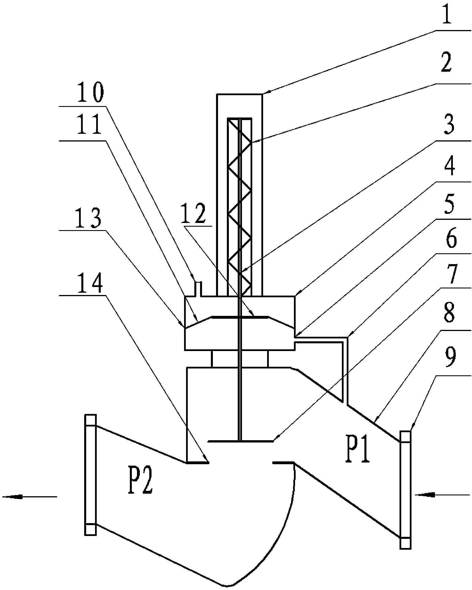
[0011] A vacuum pressure regulating valve includes a vacuum valve body 8 , a valve stem 3 , a valve core 7 , a spring 2 and an actuator 13 . The valve body 8 is welded to both ends of the valve body 8 through two DN250 flanges 9 connecting the pipelines at both ends of the vacuum control valve, so that the valve and the pipeline are integrated. Valve hole 14 for flow. The actuator 13 is fixed to the valve body 8 . The actuator 13 is composed of an upper casing 4 , a lower casing 5 , a tray 12 , a diaphragm 11 , a vent hole 10 and a pressure guide tube 6 . The diaphragm 11 is sandwiched between the assembled upper case 4 and the lower case 5, so that the upper case 4 and the lower case 5 are sealed by the diaphragm 11, and the tray 12 is arranged in the lower case 5, The air vent 10 is arranged on the upper casing 4 and communicates with the atmosphere, so that the air pressure of the upper casing is consistent with the atmospheric pressure. One end of the pressure guiding tu...


PUM


Abstract

A vacuum pressure regulating valve comprises a vacuum valve body, a valve rod, a valve element, a spring and an execution mechanism. The execution mechanism and the valve body are fixed. The execution mechanism is composed of an upper shell, a lower shell, a tray, a membrane, a vent hole and a pressure guide pipe. The membrane is arranged between the upper shell and the lower shell in a clamped mode so that the upper shell and the lower shell can be sealed by the membrane and can not be communicated with each other. The tray is arranged in the lower shell, and the vent hole is formed in the upper shell and communicated with the atmosphere. One end of the pressure guide pipe is connected and communicated with the lower shell, and the other end of the pressure guide pipe is connected and communicated with a gas inlet pipeline end inside the valve body. One end of the valve rod penetrates through the execution mechanism to be connected with one end of the spring. The other end of the spring abuts against the upper shell. The other end of the valve rod is connected with the valve element. The middle of the valve rod is connected with the tray. The valve rod drives the valve element to move through expansion and contraction changes of the spring. The vacuum pressure regulating valve needs no external energy source and can work on the occasion without electricity or gas, pressure can be conveniently set, installation is easy and reliable, the influences of the vacuum pressure regulating valve on gas inlet passageway tests can be omitted, experiment performance is reliable, and the vacuum pressure regulating valve is suitable for gas inlet passageway vacuum pumping experiments of high-speed wind holes.

Description

technical field [0001] The invention relates to the technical field of aviation aerodynamic experiments, in particular to a pressure regulating valve that realizes the vacuum suction of the main flow of the intake passage in the high-speed intake passage test. Background technique [0002] An advanced engine must be matched with an air inlet with superior performance to form a high-performance power plant. The purpose of the inlet test is to measure the static and dynamic characteristics of the inlet and provide test data for the design of the inlet to ensure that the performance of the inlet in the entire flight envelope can meet the requirements of the engine. Otherwise, the engine will surge or stop in the air. The inlet test shows that although the current ejection method helps to lengthen the working line of the inlet, the working line of the inlet of most models cannot achieve a supercritical large flow point. If the suction capacity continues to improve, it is neces...

Claims


Application Information

Patent Timeline
Patent Type & Authority Applications(China)
IPC IPC(8): F16K17/30F16K27/10
CPCF16K17/30F16K27/08F16K31/1221
Inventor 廖虹陈通林国栋李玲马晓光王旭东赵绿波程雅君
Owner AVIC SHENYANG AERODYNAMICS RES INST
Why Eureka
Try Eureka