Combustion chamber

A combustion chamber and fuel technology, applied in the field of machinery, can solve problems such as insufficient combustion of fuel, and achieve the effect of reducing the generation of harmful gases

Inactive Publication Date: 2014-08-06
王舒拉
View PDF12 Cites 0 Cited by
  • Summary
  • Abstract
  • Description
  • Claims
  • Application Information

AI Technical Summary

Problems solved by technology

[0004] The purpose of the present invention is to provide a combustion chamber for a combustion furnace to solve the problem that the fuel cannot be fully burned

Method used


Image

  • Combustion chamber
  • Combustion chamber
  • Combustion chamber

Examples


Embodiment Construction

[0029] The technical solutions of the present invention will be described in further detail below with reference to the accompanying drawings and embodiments.

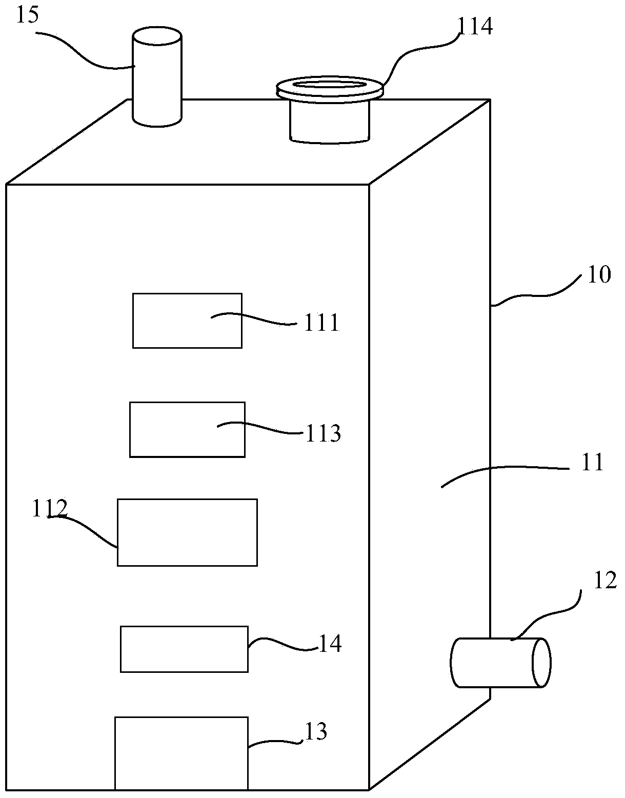
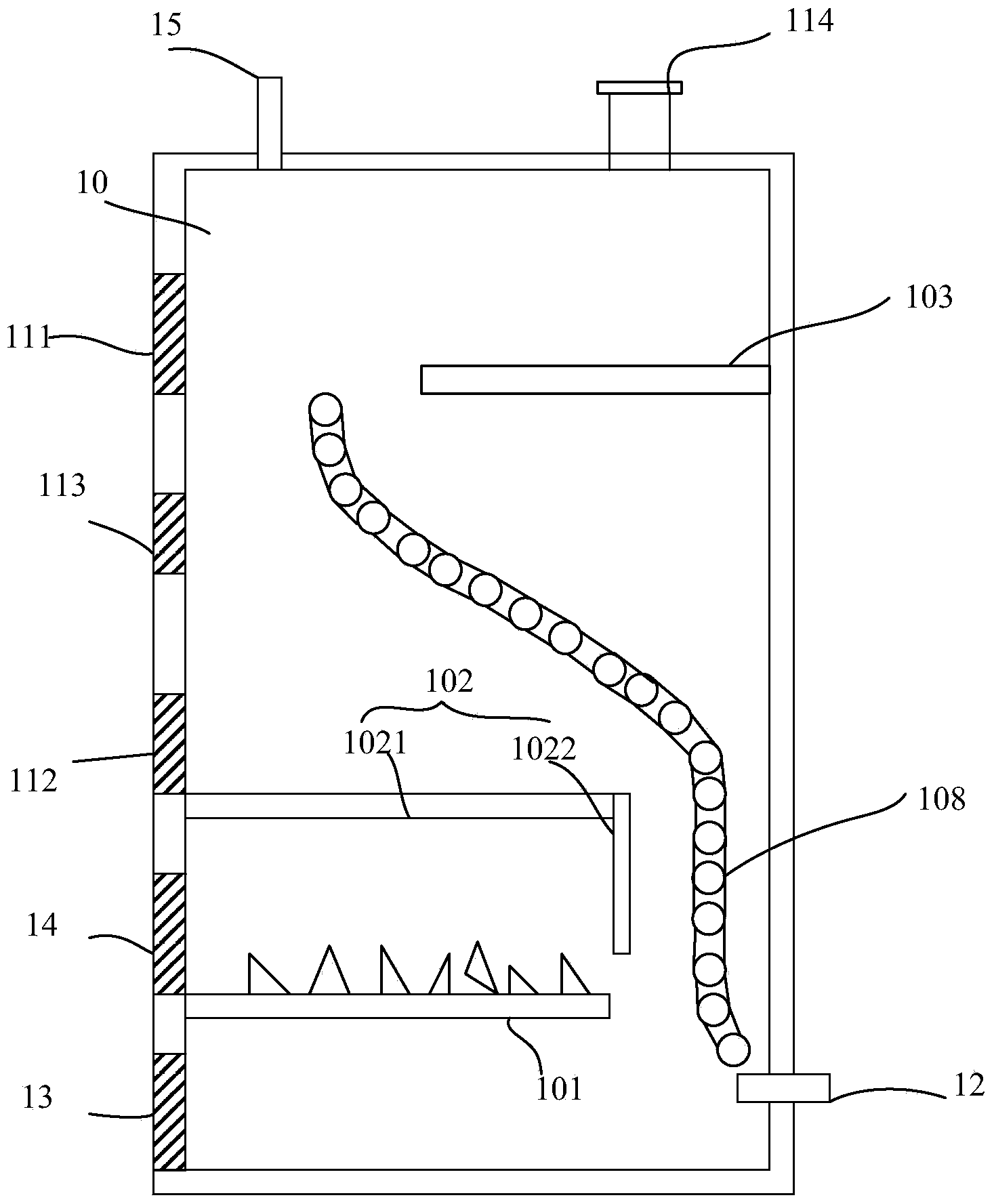
[0030] figure 1 It is an application scene of the combustion chamber provided by the present invention, that is, a schematic structural diagram of a combustion furnace including the combustion chamber. Depend on figure 1 It can be seen that the burner includes a furnace body 10 surrounded by a furnace wall 11, and a water pipe (not shown) is arranged inside the furnace body 10, and the water pipe connects / communicates with the water outlet 15 on the top of the burner and the Describe the water inlet 12 at the bottom of the burner. The furnace body 10 is in the shape of a cabinet as an example, but it is not limited thereto. The furnace body can also be in the shape of a barrel or other shapes, which is not limited.

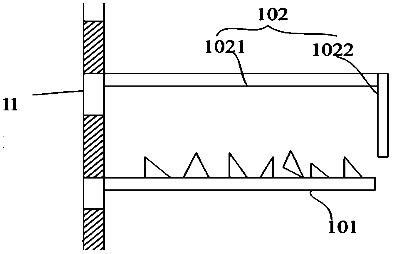
[0031] The furnace wall 11 can be a solid structure or a hollow structure. If it is a hollow struct...


PUM


Abstract

The invention provides a combustion chamber. The combustion chamber comprises a side wall, a shelf used for placing fuel, and a first stop plate arranged above the shelf. A hole is formed in the shelf. A gap for the fuel to be combusted is reserved between the first stop plate and the shelf. By means of the first stop plate, when the fuel is combusted on the shelf, the fuel combusted insufficiently is stopped and falls on the shelf again for further combustion. The combustion chamber can achieve sufficient combustion of the fuel and lower pollution.

Description

technical field [0001] The invention relates to the mechanical field, in particular to a combustion chamber for a combustion furnace. Background technique [0002] In the cold winter, many areas in the north need to use stoves for heating. In the environment where the furnace is used for heating, coal is usually used as fuel, and the heat generated by fuel combustion is used for heating, or the heat generated by fuel combustion is used to heat the water in the water pipe, and the indoor space is heated by water flow. [0003] The combustion chamber of a traditional burner usually has a very simple structure. After fuel is thrown into the burner, it is burned. However, due to insufficient fuel combustion, various problems are prone to occur. For example, insufficient fuel combustion is likely to generate carbon monoxide, causing poisoning and death of people or animals; insufficient fuel combustion is also likely to produce burning impurities, such as smoke, PM2.5 and other...

Claims


Application Information

Patent Timeline
IPC IPC(8): F24B1/183F24B1/193F24B1/192
Inventor 王舒拉
Owner 王舒拉
Why Eureka
Try Eureka