Heat transfer simplified analysis method of cluster vertical buried tube geothermal heat exchanger

A heat exchanger and geothermal technology is applied in the field of simplifying and analyzing the heat transfer of a cluster vertical buried pipe geothermal heat exchanger. Effect

Active Publication Date: 2014-08-06
SHANDONG FANGYA GSHP TECH
View PDF6 Cites 5 Cited by
  • Summary
  • Abstract
  • Description
  • Claims
  • Application Information

AI Technical Summary

Problems solved by technology

However, due to the large number of buried tube geothermal heat exchangers in large-scale ground source heat pump systems, the large number of buried tubes leads to a huge amount of calculation, which not only requires high computer hardware configuration, but also greatly increases the calculation time. The calculation of the analytical solution often takes several hours. , and the numerical solution takes days or weeks
In addition, a large number of calculation processes or tens of millions of grid nodes will also exceed the allowable calculation capacity of the computer memory, causing the computer to be paralyzed and unable to calculate
At present, there is still a lack of effective simplified analysis and calculation methods for heat transfer of large cluster buried tube geothermal heat exchangers at home and abroad

Method used


Image

  • Heat transfer simplified analysis method of cluster vertical buried tube geothermal heat exchanger
  • Heat transfer simplified analysis method of cluster vertical buried tube geothermal heat exchanger
  • Heat transfer simplified analysis method of cluster vertical buried tube geothermal heat exchanger

Examples


Embodiment Construction

[0018] The following implementations are used to illustrate the present invention, but not to limit the scope of the present invention.

[0019] see Figure 1~4 ,

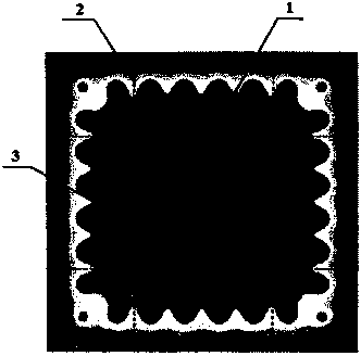
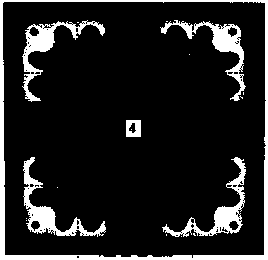
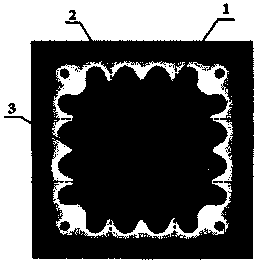
[0020] figure 1 Shown is a geothermal heat exchanger with 64 vertically buried pipes (100 meters deep) arranged in an 8×8 matrix after 16 years of operation, and the temperature field distribution in the horizontal direction of 50 meters underground. figure 1 It shows that the temperature field in the buried pipe area shows obvious periodic changes. According to the similarity of the temperature field around each buried pipe, the geothermal heat exchanger can be divided into 9 characteristic partitions ( figure 1 are separated by dotted lines).

[0021] Except for the four corner areas, the temperature field distribution around the buried pipe in the other five areas shows a certain periodical change. According to the characteristics of the temperature field symmetry plane can be regarded as an adiabatic surfac...


PUM


Abstract

The invention discloses a heat transfer simplified analysis method of a cluster vertical buried tube geothermal heat exchanger. Feature regions are divided by analyzing the change rule of an underground temperature field of a buried tube area, representative buried tubes are selected for the feature regions and are recombined to form a representative cluster vertical buried pipe geothermal heat exchanger, and heat transfer of the representative cluster vertical buried pipe geothermal heat exchanger is analyzed and calculated. After calculation is finished, a calculation result restores to an actual cluster vertical buried tube geothermal heat exchanger by the utilization of the heat exchange amount of the buried tubes and the periodicity and symmetry of changes of a rock temperature field. The calculation result obtained by the utilization of the representative cluster vertical buried pipe geothermal heat exchanger can also be popularized to any cluster vertical buried pipe geothermal heat exchanger with the same conditions and with the row number and the column number of buried tubes being no less than those of cluster vertical buried tube geothermal heat exchangers, wherein the conditions comprise geological conditions, the depth of the buried tubes, the diameter of drilled holes, backfill materials, the load borne by each buried tube, and the like. By the utilization of the method, on the basis of ensuring the heat transfer analysis result to be accurate, the computational effort is reduced remarkably.

Description

technical field [0001] The invention relates to a heat transfer analysis method of a geothermal heat exchanger of a ground source heat pump, in particular to a method for simplifying the analysis of the heat transfer of a group of vertical buried pipe geothermal heat exchangers. Background technique [0002] As a renewable energy technology, ground source heat pump technology has been widely used in my country. The geothermal heat exchanger is a key component of the ground source heat pump system and has a high initial investment. The quality of its design directly determines the economy and reliability of the ground source heat pump system. For the long-term operation of buried tube group geothermal heat exchangers, the heat transfer analysis is usually carried out based on the established single-hole buried tube heat transfer model and the linear superposition principle. At present, linear heat source model, cylindrical surface (or body) model and numerical method are mai...

Claims


Application Information

Patent Timeline
Patent Type & Authority Applications(China)
IPC IPC(8): F25B30/06
Inventor 于明志崔萍陈兆涛李洪李琳琳丛俊滋
Owner SHANDONG FANGYA GSHP TECH
Why Eureka
Try Eureka