Light guide plate and surface illumination device
A technology of a light guide plate and a light incident surface, which is applied in the directions of electric light sources, lighting devices, optical waveguides and light guides, can solve the problems of producing color spots and insufficient suppression of color spots, and achieves the goal of suppressing and reducing color spots. Effect
- Summary
- Abstract
- Description
- Claims
- Application Information
AI Technical Summary
Problems solved by technology
Method used
Image
Examples
no. 1 approach )
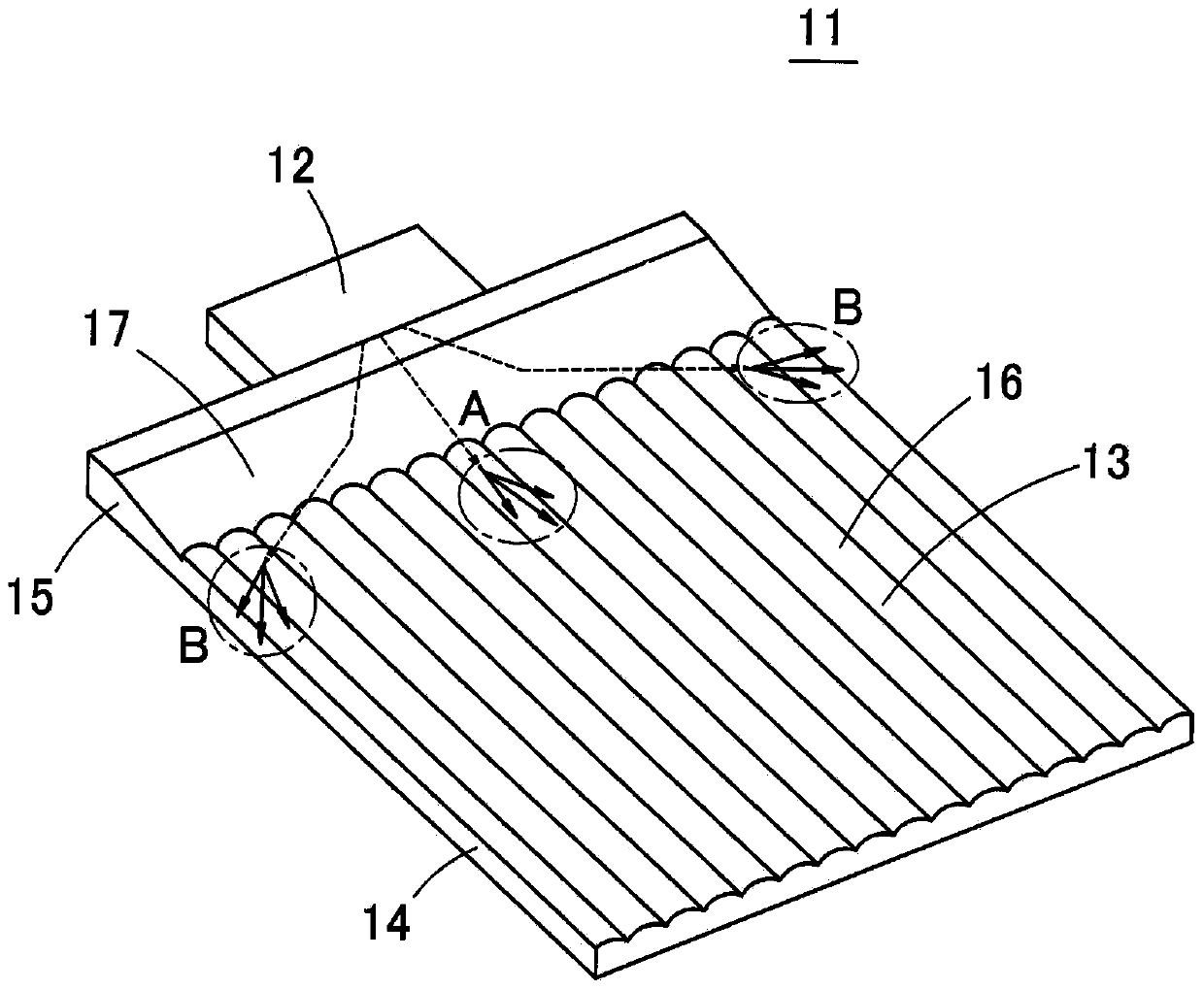
[0086] Below, refer to Figure 4 ~ Figure 8 The surface light source device 31 according to the first embodiment of the present invention will be described. Figure 4 is a perspective view showing the surface light source device 31 according to the first embodiment of the present invention, Figure 5A is its top view. in addition, Figure 5B yes Figure 5A XX-line cross-sectional view of FIG. 10 , which shows an enlarged cross-section of the lenticular lens 36 provided on the surface of the light guide plate 33 . Figure 6 It is a schematic cross-sectional view obtained when the surface light source device 31 is cut longitudinally, and shows the trajectories of light rays in a plane perpendicular to the light incident surface 38 and the light exit surface 39 of the light guide plate 33 . Figure 7 It is a diagram showing a cross section of the directivity conversion pattern 40 on a cross section parallel to the light incident surface 38 of the light guide plate 33 , and sh...
no. 2 approach )
[0120] Figure 19 It is a perspective view showing the surface light source device 61 according to the second embodiment of the present invention. Figure 20 It is a plan view of the surface light source device 61 . Figure 21 The cross-sectional shape of the directivity conversion pattern 40 on a cross-section parallel to the light incident surface 38 is shown. In addition, in Figure 21 In , a part of the directivity conversion pattern 40 is enlarged and shown.
[0121] In the surface light source device 61 according to the second embodiment of the present invention, in the vicinity of the optical axis C of the point light source 32 , the directivity conversion pattern 40 is partially removed to form a flat surface 62 (mirror surface). In particular, in the illustrated example, triangular flat surfaces 62 sandwiched between the left and right directivity conversion patterns 40 are provided.
[0122] Such as Figure 21 As shown, in the left and right directivity conversion...
no. 3 approach )
[0126] Figure 23 It is a perspective view of a surface light source device 71 according to a third embodiment of the present invention. Figure 24A is a plan view of the surface light source device 71 . Figure 24B yes Figure 24A The Y-Y line profile.
[0127] In the surface light source device 71 of the third embodiment, a light diffusion pattern 72 for laterally diffusing the directivity of reflected light is further formed on the upper surface and / or the lower surface of the light introduction portion 35 . Such as Figure 24B As shown, the light diffusion pattern 72 may be a pattern in which V-grooves 72a extending vertically are arranged parallel to each other, or may be a lenticular pattern or a pattern of any shape. In this structure, the light is diffused laterally by the light diffusion pattern 72 and directed toward the side surface of the light guide plate 33 , thereby preventing the side edge portion of the light exit surface 39 from being darkened. Furthermo...
PUM
| Property | Measurement | Unit |
|---|---|---|
| Length | aaaaa | aaaaa |
Abstract
Description
Claims
Application Information
 - R&D
- Intellectual Property
- Life Sciences
- Materials
- Tech Scout
- Unparalleled Data Quality
- Higher Quality Content
- 60% Fewer Hallucinations
Browse by: Latest US Patents, China's latest patents, Technical Efficacy Thesaurus, Application Domain, Technology Topic, Popular Technical Reports.
© 2025 PatSnap. All rights reserved.Legal|Privacy policy|Modern Slavery Act Transparency Statement|Sitemap|About US| Contact US: help@patsnap.com


