Supercharge Your Innovation With Domain-Expert AI Agents!
Multi-exposure visual field splicing system and method
What is Al technical title?
Al technical title is built by PatSnap Al team. It summarizes the technical point description of the patent document.
A field of view splicing, multi-exposure technology, applied in the semiconductor field, can solve the problems of single splicing method and inability to combine
Active Publication Date: 2014-08-06
SHANGHAI MICRO ELECTRONICS EQUIP (GRP) CO LTD
View PDF12 Cites 2 Cited by
Summary
Abstract
Description
Claims
Application Information
AI Technical Summary
This helps you quickly interpret patents by identifying the three key elements:
Problems solved by technology
Method used
Benefits of technology
Problems solved by technology
[0007] The present invention provides a multi-exposure field of view splicing system and method, which solves the problem that the splicing method of the same size exposure field of view is single and cannot be combined according to the use requirements under the premise that the number of splicing remains unchanged.
Method used
Image
Click on the blue label to locate the original text in one second.
Reading with bidirectional positioning of images and text.
Examples
Embodiment 1
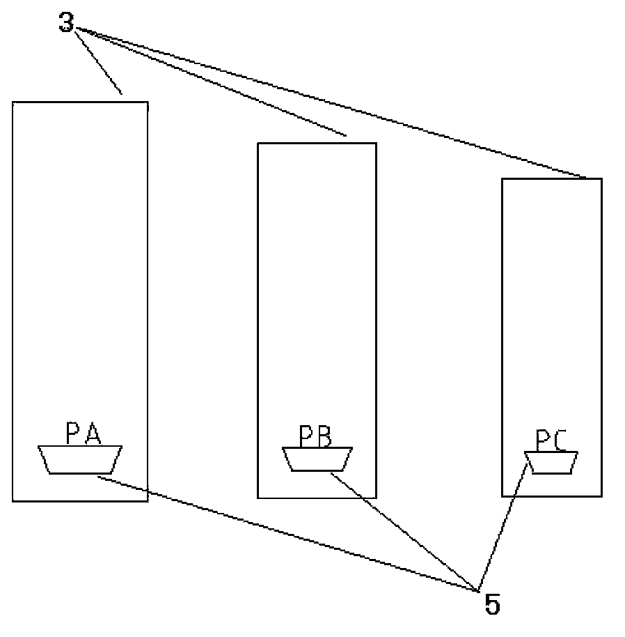
[0065] Such as image 3 As shown, a multi-exposure field of view splicing method forms three different exposure fields of PA, PB and PC, wherein the width PA=width PB=width PC, PA=100mm, PB=130mm, PC =160mm.
[0066] When the number of exposure fields N=5,
[0067] It is spliced by 1 PA, 2 PB, and 2 PCs. The size of the spliced field of view: 1*PA+2*PB+2*PC=1*160+2*130+2*100=620mm.
Embodiment 2
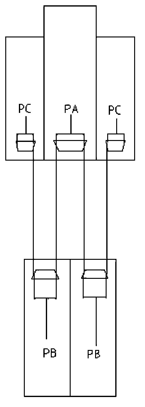
[0069] Such as Figure 4 As shown, a multi-exposure field of view splicing method forms three different exposure fields of PA, PB and PC, wherein the width PA=width PB=width PC, PA=100mm, PB=130mm, PC= 160mm.
[0070] When the number of exposure fields N=5,
[0071] It is spliced by 1 PA, 3 PB, and 1 PC. The size of the spliced field of view: 1*PA+3*PB+1*PC=1*160+3*130+1*100=650mm.
Embodiment 3
[0073] Such as Figure 5 As shown, a multi-exposure field of view splicing method forms three different exposure fields of PA, PB and PC, wherein the width PA=width PB=width PC, PA=100mm, PB=130mm, PC= 160mm.
[0074] When the number of exposure fields N=5,
[0075] It is spliced by 2 PAs, 2 PBs, and 1 PC. The size of the spliced field of view: 2*PA+2*PB+1*PC=2*160+2*130+1*100=680mm.
[0076] It can be concluded from [Example 1], [Example 2] and [Example 3] that when the number N of the exposure fields of view is an odd number, the exposure fields of view are spliced according to the following formula to form three different Stitched field of view:
PUM
Abstract
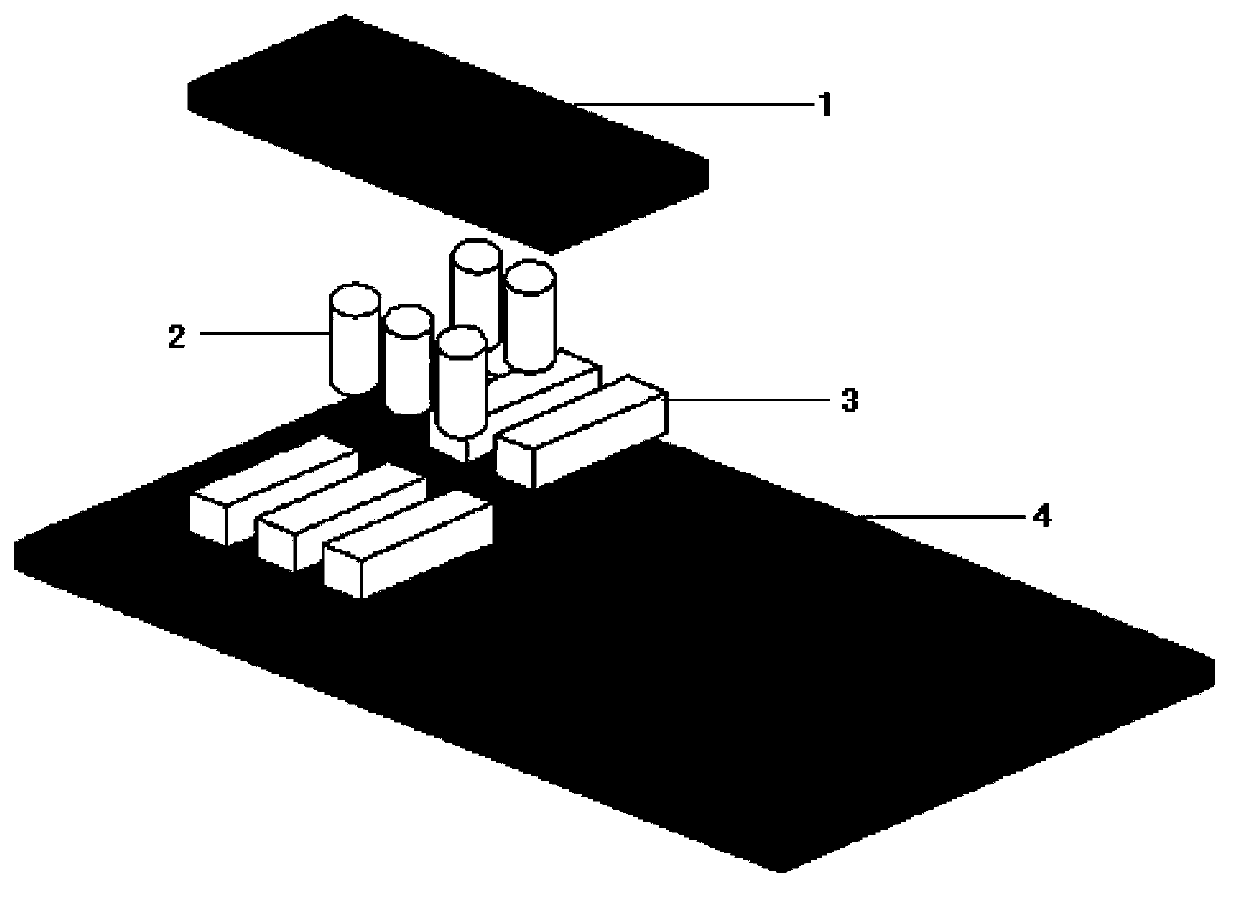
The present invention provides a multi-exposure visual field splicing system and a method. The system comprises: a mask, wherein the mask is provided with images with different sizes; a plurality of illumination units, wherein the plurality of the illumination units irradiate the images on the mask so as to form a plurality of imaging units, and each imaging unit comprises an exposure visual field; and a substrate, wherein the plurality of the exposure visual fields are spliced on the substrate to form a splicing visual field, the exposure visual fields comprise an exposure visual field PA, a corresponding exposure visual field width PA, an exposure visual field PB, a corresponding exposure visual field width PB, an exposure visual field PC and a corresponding exposure visual field width PC, PA is more than PB, PB is more than PC, and the width PA, the width PB and the width PC are equal. According to the present invention, the exposure visual field splicing method is flexible, different splicing methods can be selected according to different requirements of different products on the splicing visual field size, and the splicing market with more splicing sizes is provided.
Description
technical field [0001] The invention relates to the field of semiconductors, in particular to a multi-exposure field of view splicing system and method. Background technique [0002] In the semiconductor manufacturing process, the lithographymachine needs to increase the exposure size of the liquid crystal panel by increasing the field of view of a single optical system, or by using multiple small local projection optical systems instead of a single large projection optical system. [0003] In the existing technology, the method of using multiple small local projection optical systems instead of a single large projection optical system can continuously increase the number of spliced fields of view to meet the needs of high-generation large-size panels, and at the same time, it can be used for masks and substrates. The deformation is compensated in different regions to improve the image quality, so it has obvious advantages and is widely used. [0004] Patent No. JPA20013...
Claims
Application Information
Patent Timeline
Application Date:The date an application was filed.
Publication Date:The date a patent or application was officially published.
First Publication Date:The earliest publication date of a patent with the same application number.
Issue Date:Publication date of the patent grant document.
PCT Entry Date:The Entry date of PCT National Phase.
Estimated Expiry Date:The statutory expiry date of a patent right according to the Patent Law, and it is the longest term of protection that the patent right can achieve without the termination of the patent right due to other reasons(Term extension factor has been taken into account ).
Invalid Date:Actual expiry date is based on effective date or publication date of legal transaction data of invalid patent.
IPC IPC(8): G03F7/20
Inventor 武珩
Owner SHANGHAI MICRO ELECTRONICS EQUIP (GRP) CO LTD
