Panoramic gaze camera space calibration method based on image splicing

A technology of camera space and image stitching, applied in image enhancement, image analysis, image data processing, etc., can solve the problems of limited shooting range and inability to take into account multiple different scenes at the same time

Active Publication Date: 2014-08-06
NAT UNIV OF DEFENSE TECH
View PDF3 Cites 19 Cited by
  • Summary
  • Abstract
  • Description
  • Claims
  • Application Information

AI Technical Summary

Problems solved by technology

However, its shooting range is limited, and it cannot tak

Method used


Image

  • Panoramic gaze camera space calibration method based on image splicing
  • Panoramic gaze camera space calibration method based on image splicing
  • Panoramic gaze camera space calibration method based on image splicing

Examples


Embodiment Construction

[0051] The present invention will be further described in detail below in conjunction with examples and accompanying drawings.

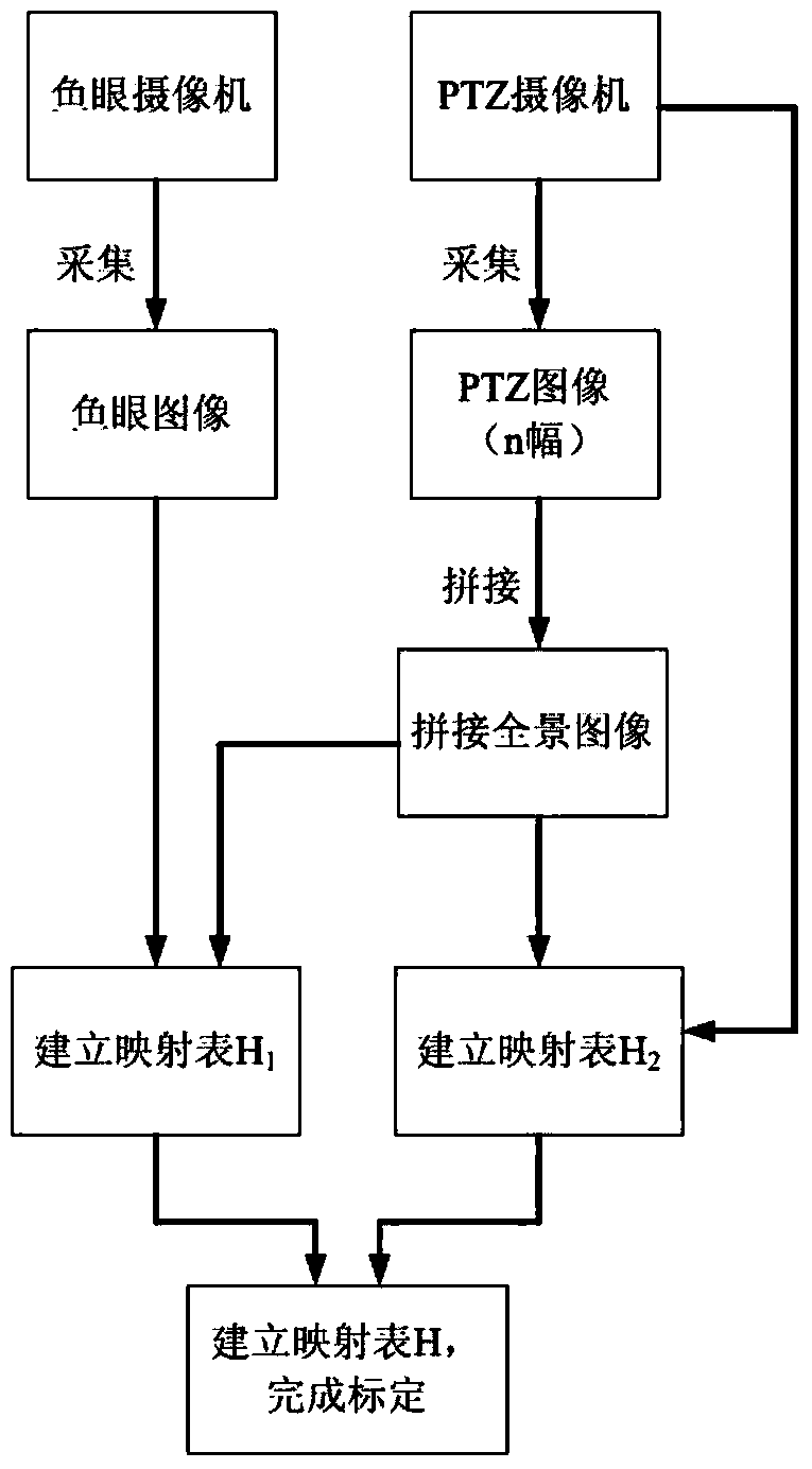
[0052] Such as image 3 Shown is a flow chart of a spatial calibration method based on panoramic image mosaic for panoramic staring cameras disclosed in the present invention. First, establish the rotation model of the PTZ camera. Such as Figure 4 As shown, the PTZ camera coordinate system O-XYZ is established with the optical center O of the PTZ camera as the origin, assuming that the principal point of the PTZ camera is P 0 , then OP 0 It is the optical axis of the PTZ camera. Suppose P 0 The yaw and pitch angles of the point are and θ 0 , then P 0 The coordinate value of the point (x 0 ,y 0 ,z 0 ) is calculated as follows:

[0053]

[0054] Among them, f is the focal length of the PTZ camera.

[0055] PTZ image captured by PTZ camera I PTZ The center point O' of the image coordinate system O'-UV is established as the origin. fo...


PUM


Abstract

The invention discloses a panoramic gaze camera space calibration method based on image splicing. The method includes the steps that firstly, a rotation model of a PTZ camera in a panoramic speed dome is built; secondly, multiple PTZ images shot by the PTZ camera and including all information of scenes are spliced to acquire a panoramic image; thirdly, based on the panoramic image, a mapping relation H2 between pixel points of the panoramic image and motion parameters of the PTZ camera and a mapping relation H1 between the pixel points of the panoramic image and pixel points in a fisheye image are built; fourthly, based on the mapping relation H1 and the mapping relation H2, a mapping relation H between the pixel points of the fisheye image and the motion parameters of the PTZ camera is built, and then panoramic gaze camera space calibration is achieved. By the adoption of the method, a horizontal deflection angle and a vertical deflection angle of the PIZ camera in the panoramic gaze camera can be accurately controlled, the monitoring position of a region of interest of the fisheye image shot by a selected fisheye camera is made to be at the center of the image shot by the PTZ camera, and then accurate positioning monitoring is achieved.

Description

Technical field: [0001] The invention relates to an image calibration method, in particular to an image mosaic-based panoramic gaze camera space calibration method, which belongs to the field of image information processing. Background technique: [0002] At present, in the field of security monitoring, a large number of cameras are installed in various places such as government buildings, military bases, banks, schools, shopping malls, prisons, parking lots, ports, and urban streets. In addition, in other application fields, such as video conferencing, In the fields of distance education, robot navigation, and robot navigation, the application of cameras is also expanding. However, with the large-scale popularization and application of cameras, the deficiencies of traditional cameras are gradually exposed. Due to the limited shooting range, the traditional camera can only see a small part of the scene in front of the camera, so there are monitoring blind spots and monitori...

Claims


Application Information

Patent Timeline
IPC IPC(8): G06T7/00G06T5/50G06T3/40
Inventor 刘煜张茂军左承林王炜徐玮
Owner NAT UNIV OF DEFENSE TECH
Why Eureka
Try Eureka