Rotary device with antenna

An antenna rotation device and antenna technology, applied in the direction of antennas, electrical components, etc., can solve the problems of antenna structure without angle restrictions, easy to be affected by external forces, and frustration, so as to improve communication quality, better operation feel, and reduce labor costs. Effect

Active Publication Date: 2014-08-06
WISTRON NEWEB +1
View PDF5 Cites 11 Cited by
  • Summary
  • Abstract
  • Description
  • Claims
  • Application Information

AI Technical Summary

Problems solved by technology

[0006] In order to solve the problem that the known antenna structure has no angle limit during rotation and is easily affected by external forces, the main purpose of the present invention is to provide an antenna rotation device that can realize rotation limitation to limit the rotation angle of the antenna and has a sense of frustration when rotating

Method used


Image

  • Rotary device with antenna
  • Rotary device with antenna
  • Rotary device with antenna

Examples


Embodiment Construction

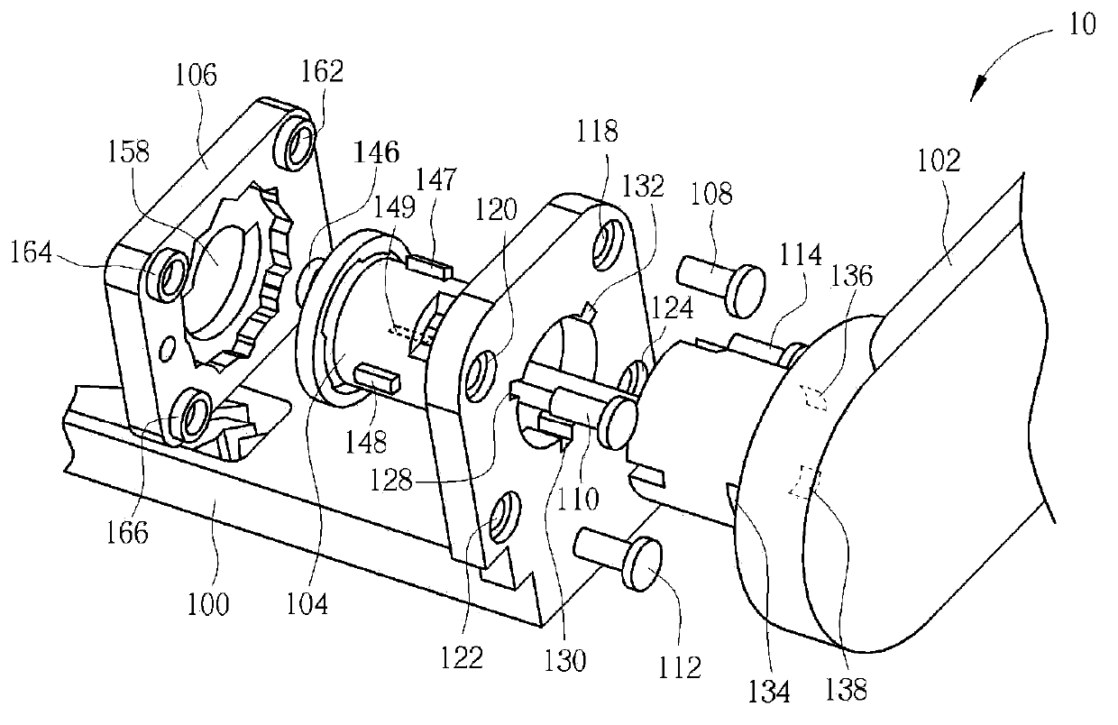
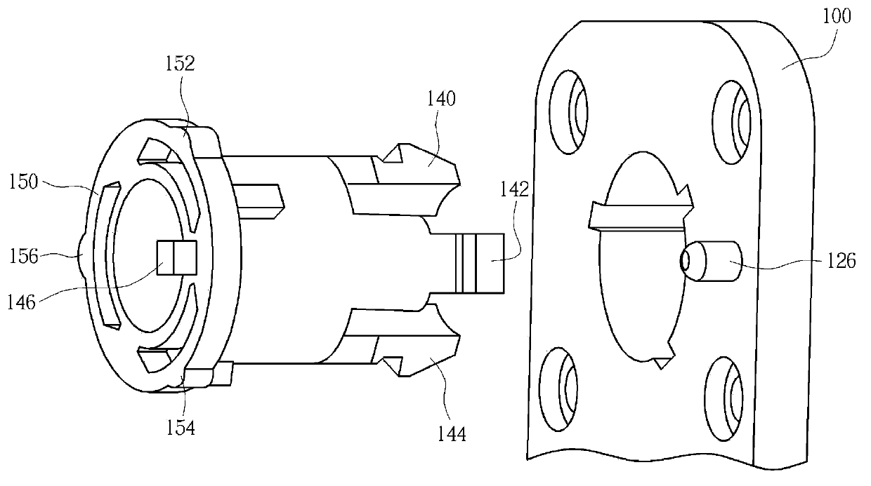
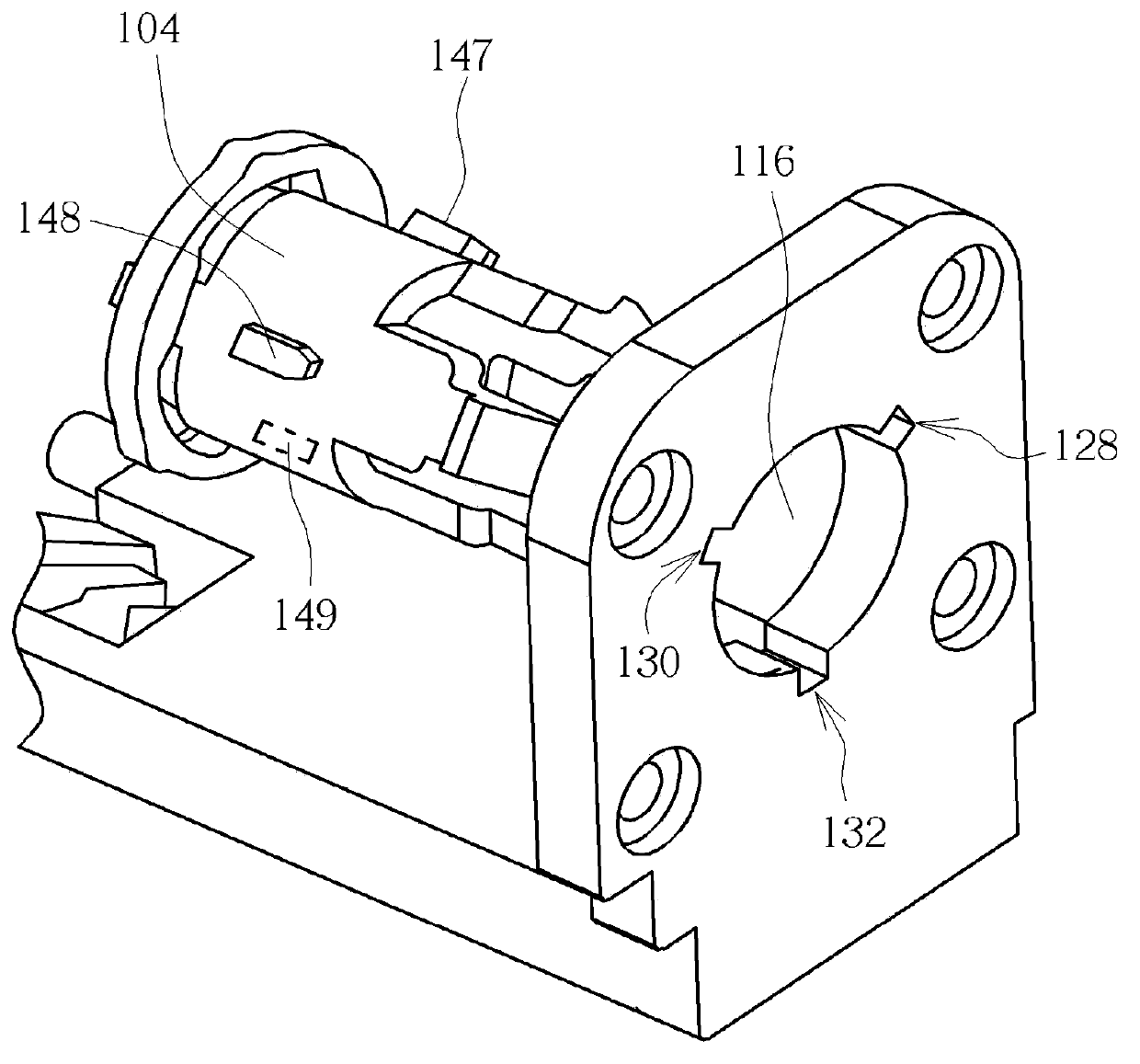
[0040] Please refer to Figure 1A and Figure 1B , Figure 1A is a schematic diagram of an antenna rotation device 10 according to an embodiment of the present invention, Figure 1B It is a schematic diagram of another viewing angle of the antenna rotation device 10 . The antenna rotating device 10 includes a base 100 , an antenna 102 , a cylindrical rotating shaft 104 , a limiting cover 106 and screws 108 , 110 , 112 , 114 . The base 100 has a circular slot structure 116 , screw holes 118 , 120 , 122 , 124 and an initial positioning pin 126 . The antenna 102 includes tenon slots 134 , 136 , 138 , and the cylindrical shaft 104 includes tenons 140 , 142 , 144 corresponding to the tenon slots 134 , 136 , 138 . When assembling, the tenon 140, 142, 144 can be fixed in the tenon groove 134, 136, 138 respectively, so as to fix the cylindrical shaft 104 and the antenna 102 together, so that when the antenna 102 rotates, it will drive the cylindrical The shaft 104 rotates.

[0041...


PUM


Abstract

The invention discloses a rotary device with an antenna. The rotary device comprises the antenna, a base, a cylindrical rotary shaft and a limiting cover. The base is provided with a circular slot structure; the cylindrical rotary shaft is provided with a limiting protruded structure and penetrates the circular slot structure to be connected to the antenna, so that the cylindrical rotary shaft and the antenna can be fixed to the base and can rotate along a rotation axis; the limiting cover is arranged on the base and is provided with a limiting groove corresponding to the limiting protruded structure; the limiting protruded structure can rotate in the limiting groove, and a rotation range of the limiting protruded structure is constrained in the limiting groove, so that the cylindrical rotary shaft can be constrained at an angle when rotating along the rotation axis. The rotary device has the advantages that the antenna can be adjusted until an angle of the antenna is proper, so that the communication quality can be improved; the antenna can be adjusted and fixed at the proper angle, accordingly, a user feels rhythmic when the rotary device rotates and feels good when the user operates the rotary device, the rotary device can be conveniently and quickly mounted, and the labor cost can be reduced.

Description

technical field [0001] The invention relates to an antenna rotation device, in particular to an antenna rotation device which can limit the rotation angle of the antenna and has a sense of frustration when rotating. Background technique [0002] Antenna is one of the most important components in a wireless communication device, which can be used to transmit and receive electromagnetic wave signals, so as to realize the purpose of exchange and transmission of wireless communication. Generally, different wireless communication device applications will be equipped with antennas corresponding to the types and characteristic requirements. Since the performance of the antenna will greatly affect the communication quality, the user must adjust the antenna to a proper position to transmit and receive signals, so as to achieve the best transmission performance of the antenna. [0003] In order to allow the user to smoothly adjust the antenna to a proper position and angle, known ant...

Claims


Application Information

Patent Timeline
Patent Type & Authority Applications(China)
IPC IPC(8): H01Q3/02H01Q3/06
Inventor 陆利杨帆
Owner WISTRON NEWEB
Why Eureka
Try Eureka