
Method for two-way wireless transmission of energy and information
A technology of wireless transmission and energy, which is applied in the field of wireless transmission, can solve the problems of two-way transmission of information, etc., achieve the effect of improving automation level, realizing constant power wireless transmission, and avoiding waste
- Summary
- Abstract
- Description
- Claims
- Application Information
AI Technical Summary
Problems solved by technology
Method used
Image

Examples
specific Embodiment approach 1
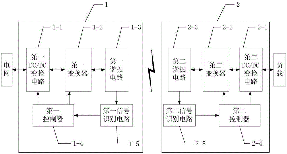
[0013] Specific implementation mode one: the following combination figure 1 Describe this embodiment. The method for two-way wireless transmission of energy and information described in this embodiment is implemented based on a wireless transmission device. The wireless transmission device includes a grid-side wireless energy device 1 and a load-side wireless energy device 2. The grid-side wireless The electrical signal input end of the energy device 1 is coupled and connected to the electrical signal output end of the power grid, the grid side wireless energy device 1 and the load side wireless energy device 2 are wirelessly connected through magnetic coupling, and the load side wireless energy device 2 is connected to the load;
[0014] The grid-side wireless energy device 1 includes a first DC / DC conversion circuit 1-1, a first converter 1-2, a first resonant circuit 1-3, a first controller 1-4 and a first signal identification circuit 1 -5; the load side wireless energy de...
specific Embodiment approach 2
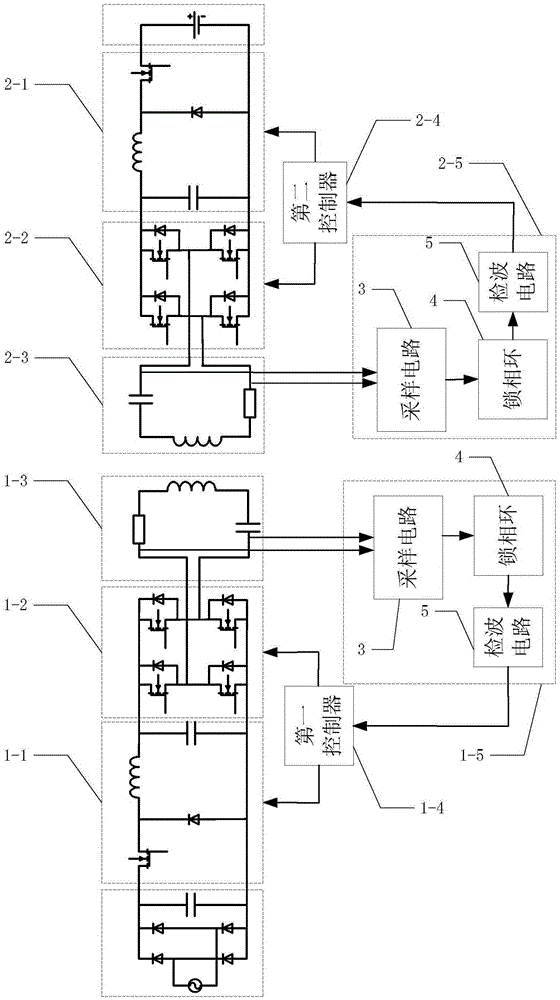
[0018] Specific implementation mode two: the following combination figure 2 Describe this embodiment mode. This embodiment mode will further explain Embodiment 1. The first DC / DC conversion circuit 1-1 and the second DC / DC conversion circuit 2-1 have the same structure, both of which are step-down conversion circuits. A step-down switch is provided in the voltage conversion circuit, and the identification code switch signals received by the first DC / DC conversion circuit 1-1 and the second DC / DC conversion circuit 2-1 are input to the step-down switch.
[0019] In this implementation manner, the step-down conversion circuits are all Buck step-down circuits. The first DC / DC conversion circuit 1-1 and the second DC / DC conversion circuit 2-1 may also be Boost voltage boosting circuits or Buck-Boost voltage-boosting circuits.
specific Embodiment approach 3
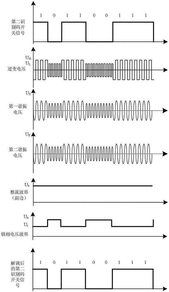
[0020] Specific implementation mode three: the following combination figure 2 Describe this embodiment mode, this embodiment mode will further explain Embodiment 1, the structure of described first signal recognition circuit 1-5 and second signal recognition circuit 2-5 are the same, all comprise sampling circuit 3, phase-locked loop 4 and wave detection The circuit 5 and the sampling circuit 3 sample the AC signal output by the first resonant circuit 1-3 or the second resonant circuit 2-3, and the sampled electrical signal is output to the phase-locked loop 4 for phase comparison, and the frequency and frequency are obtained The corresponding phase-locked voltage waveform is filtered by the detection circuit 5 to obtain the identification code switch signal.
PUM
 Abstract
Description
Claims
Application Information