
Energy/information two-way wireless transmission method

A wireless transmission and energy technology, applied in the field of wireless transmission, can solve the problem of inability to transmit information in both directions, and achieve the effect of improving the level of automation, avoiding waste, and realizing constant power wireless transmission.

Inactive Publication Date: 2014-08-06
HARBIN INST OF TECH
View PDF2 Cites 17 Cited by
  • Summary
  • Abstract
  • Description
  • Claims
  • Application Information

AI Technical Summary

Problems solved by technology

[0003] The purpose of the present invention is to solve the problem that the existing wireless transmission technology cannot realize the two-way transmission of information while realizing the two-way transmission of energy, and provides a method for two-way wireless transmission of energy and information

Method used


Image

  • Energy/information two-way wireless transmission method
  • Energy/information two-way wireless transmission method
  • Energy/information two-way wireless transmission method

Examples


specific Embodiment approach 1

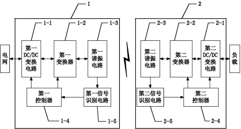
[0013] Specific implementation mode one: the following combination figure 1 Describe this embodiment. The method for two-way wireless transmission of energy and information described in this embodiment is implemented based on a wireless transmission device. The wireless transmission device includes a grid-side wireless energy device 1 and a load-side wireless energy device 2. The grid-side wireless The electrical signal input end of the energy device 1 is coupled and connected to the electrical signal output end of the power grid, the grid side wireless energy device 1 and the load side wireless energy device 2 are wirelessly connected through magnetic coupling, and the load side wireless energy device 2 is connected to the load;

[0014] The grid-side wireless energy device 1 includes a first DC / DC conversion circuit 1-1, a first converter 1-2, a first resonant circuit 1-3, a first controller 1-4 and a first signal identification circuit 1 -5; the load side wireless energy de...

specific Embodiment approach 2

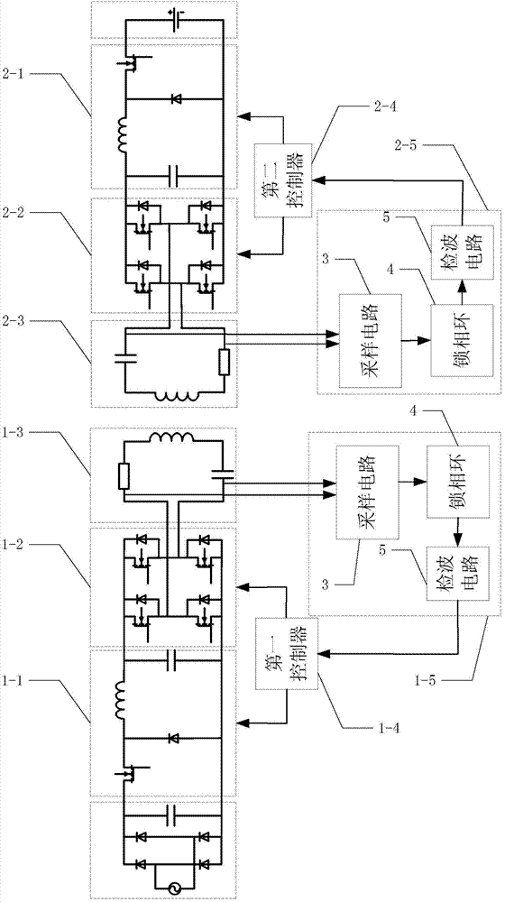
[0018] Specific implementation mode two: the following combination figure 2 Describe this embodiment mode. This embodiment mode will further explain Embodiment 1. The first DC / DC conversion circuit 1-1 and the second DC / DC conversion circuit 2-1 have the same structure, both of which are step-down conversion circuits. A step-down switch is provided in the voltage conversion circuit, and the identification code switch signals received by the first DC / DC conversion circuit 1-1 and the second DC / DC conversion circuit 2-1 are input to the step-down switch.

[0019] In this implementation manner, the step-down conversion circuits are all Buck step-down circuits. The first DC / DC conversion circuit 1-1 and the second DC / DC conversion circuit 2-1 may also be Boost voltage boosting circuits or Buck-Boost voltage-boosting circuits.

specific Embodiment approach 3

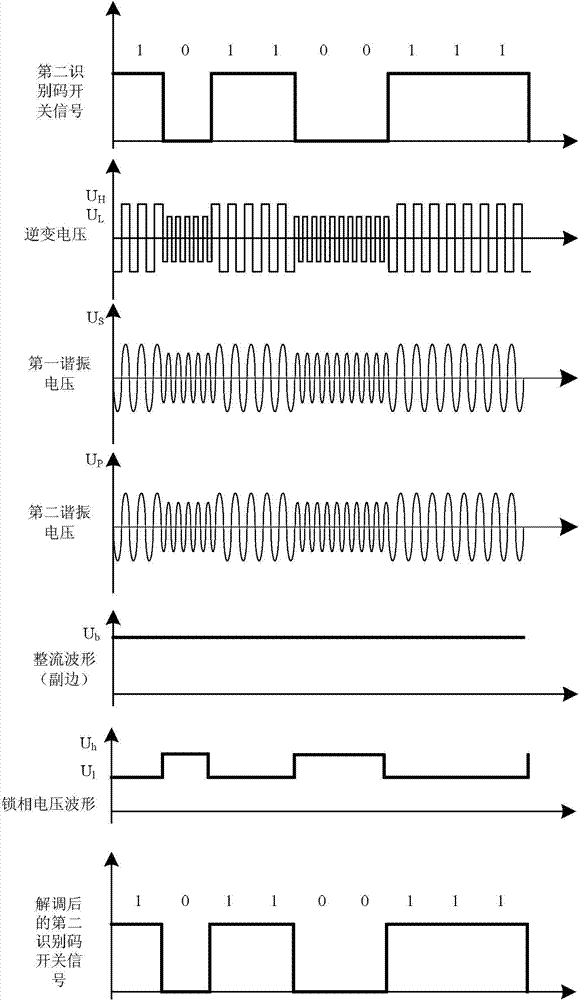
[0020] Specific implementation mode three: the following combination figure 2 Describe this embodiment mode, this embodiment mode will further explain Embodiment 1, the structure of described first signal recognition circuit 1-5 and second signal recognition circuit 2-5 are the same, all comprise sampling circuit 3, phase-locked loop 4 and wave detection The circuit 5 and the sampling circuit 3 sample the AC signal output by the first resonant circuit 1-3 or the second resonant circuit 2-3, and the sampled electrical signal is output to the phase-locked loop 4 for phase comparison, and the frequency and frequency are obtained The corresponding phase-locked voltage waveform is filtered by the detection circuit 5 to obtain the identification code switch signal.


PUM


Abstract

The invention relates to an energy / information two-way wireless transmission method, belonging to the field of wireless transmission. The method solves the problem that the existing wireless transmission technique can not simultaneously implement energy two-way transmission and information two-way transmission. The method is implemented on the basis of a wireless transmission device. The wireless transmission device comprises a network side wireless energy device and a load side wireless energy device, wherein an electric signal input end of the network side wireless energy device is coupled and connected with an electric signal output end of an electric network; the network side wireless energy device is wirelessly connected with the load side wireless energy device in a magnetic coupling mode; the load side wireless energy device is connected with a load; the network side wireless energy device comprises a first DC / DC conversion circuit, a first convertor, a first resonance circuit, a first controller and a first signal identification circuit; and the load side wireless energy device comprises a second DC / DC conversion circuit, a second convertor, a second resonance circuit, a second controller and a second signal identification circuit. The method is used in wireless transmission.

Description

technical field [0001] The invention relates to a method for two-way wireless transmission of energy and information, belonging to the field of wireless transmission. Background technique [0002] With the consumption of natural resources and the development of technology, the use of electric vehicles will definitely become a trend in the future. V2G (Vehicle-to-grid) describes such a system: when the hybrid electric vehicle or the pure electric vehicle is not running, the electric motor connected to the grid transmits energy to the grid, and in turn, when the electric vehicle When the battery needs charging, current can be drawn from the grid to feed the battery. However, the traditional implementation of V2G adopts plug-in charging and discharging, which has problems such as unsafe, easy aging, and inconvenient. Therefore, the application of wireless energy transmission in the field of electric vehicle battery charging has greatly improved the level of intelligence. Wit...

Claims


Application Information

Patent Timeline
Patent Type & Authority Applications(China)
IPC IPC(8): H02J17/00H02J50/12
Inventor 朱春波张剑韬宋凯魏国逯仁贵郭宗芝
Owner HARBIN INST OF TECH
Learn More