
Wire-rod and the like hot-rolling machine

A technology for hot rolling mills and wire rods, applied to metal rolling stands, metal rolling mill stands, cantilevered rolling mill stands, etc., which can solve the problems of increased number of machines and high operating costs

Inactive Publication Date: 2014-08-06
PERT
View PDF5 Cites 3 Cited by
  • Summary
  • Abstract
  • Description
  • Claims
  • Application Information

AI Technical Summary

Problems solved by technology

[0013] While ensuring a significant increase in hourly productivity, the tree structure of the hot rolling line leads to a significant increase in the number of machines involved in the wire rod production process, resulting in higher operating costs

Method used


Image

  • Wire-rod and the like hot-rolling machine
  • Wire-rod and the like hot-rolling machine
  • Wire-rod and the like hot-rolling machine

Examples


Embodiment Construction

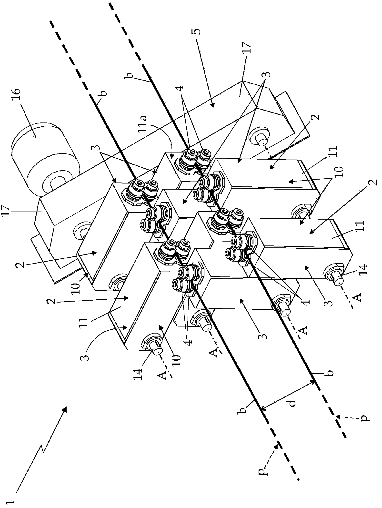
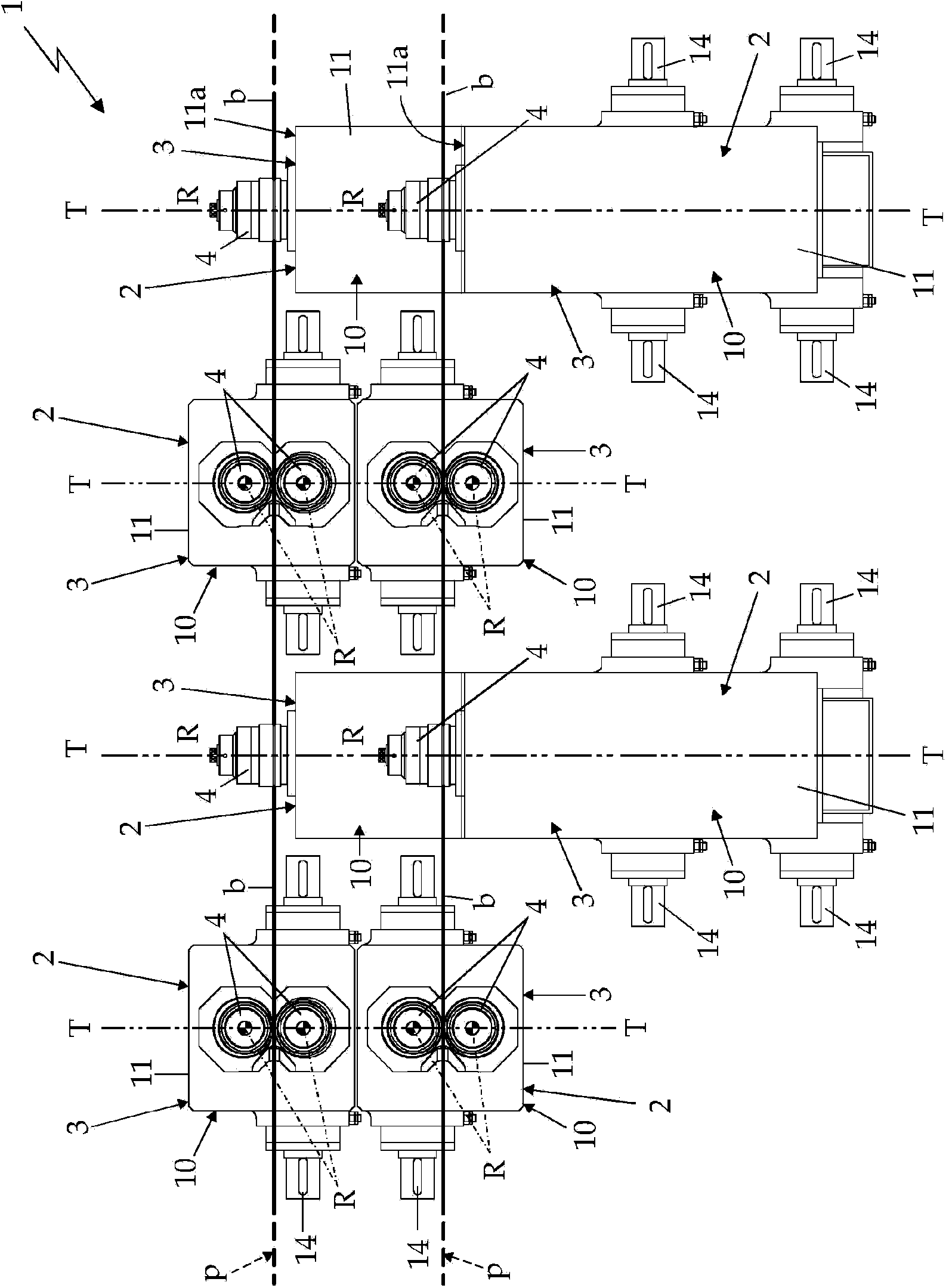
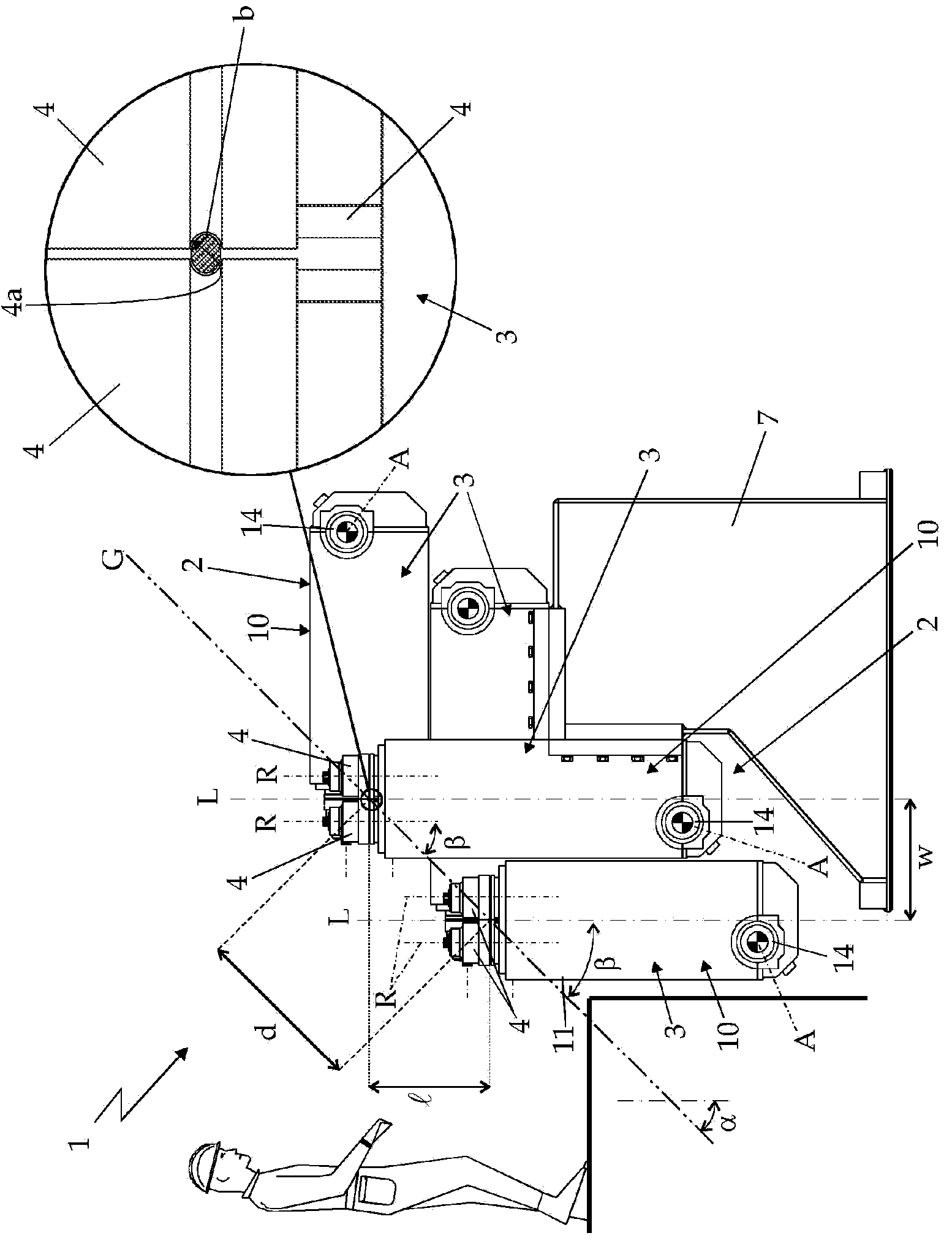
[0023] refer to figure 1 , figure 2 as well as image 3 , reference number 1 designates as a whole a machine for hot rolling two metal wires b or similar semi-finished products in parallel and at high temperature, this hot rolling mill is particularly advantageously used for the production of wires for reinforced concrete.

[0024] More specifically, the machine 1 is configured to hot-roll two metal wires b in parallel, which are fed into the machine side-by-side along respective feed paths p, which are locally substantially straight and close to each other. parallel.

[0025] In other words, the feed paths p of the two wires b lie on the same lying plane G and are arranged at a predetermined distance d from each other, preferably but not necessarily within a distance ranging from 0.3 meters to 3 meters.

[0026] In the example shown, in particular, the feed paths p of the two wires b extend preferably, but not necessarily, in the horizontal direction, while the lying plan...


PUM


Abstract

Wire-rod hot-rolling machine (1) which comprises a plurality of roller- provided rolling units (2) which are arranged one after the other along the wire-rod feeding paths (p); the roller-provided rolling unit (2) being formed by a plurality of rolling-mills assemblies (3) each of which is provided with a pair of opposite, counter-rotating rolling mill rollers (4), which are arranged parallel and adjacent each other; said rolling- mills assemblies (3) being arranged one beside the other, coplanar to a corresponding reference plane locally perpendicular to the feeding paths (p), each at the feeding path (p) of a respective wire rod (b), and are oriented so that the rotation axes (R) of the rolling mill rollers (4) of the various rolling- mills assemblies (3) are locally parallel to one another while intersecting the lying plane of the feeding paths (p) of the wire rods with an inclination angle (3) greater than 5 DEG and smaller than 85 DEG.

Description

technical field [0001] The invention relates to a hot rolling mill for wire rod and similar materials. [0002] In more detail, the invention relates to a machine for the production of hot-rolled wire for reinforced concrete. The use of the following description expressly refers to the machine without implying any loss of generality. Background technique [0003] As is known, wire rods for reinforced concrete are obtained by subjecting steel wire rods having a substantially circular cross-section to a hot-rolling process which progressively reduces the nominal cross-section of the wire rods. [0004] The hot rolling line used to carry out this special smelting process usually consists of an appropriate number of rolling units equipped with rolls, which are arranged sequentially along the feed path of the wire so that each rolling unit equipped with rolls The units are all capable of slightly reducing the nominal cross-section of the high temperature steel wire while it is ...

Claims


Application Information

Patent Timeline
Patent Type & Authority Applications(China)
IPC IPC(8): B21B1/18
CPCB21B13/103B21B1/18B21B13/005B21B35/02B21B1/163
Inventor 克劳迪奥·通巴马西米亚诺·祖卡托
Owner PERT
Learn More