
Catheter having flat beam deflection tip with fiber puller members

A catheter and component technology, applied in the field of deflectable catheters, can solve problems such as high cost, easy to break, and weaken

Active Publication Date: 2014-08-13
BIOSENSE WEBSTER (ISRAEL) LTD
View PDF7 Cites 0 Cited by
  • Summary
  • Abstract
  • Description
  • Claims
  • Application Information

AI Technical Summary

Problems solved by technology

However, metal and stainless steel puller wires, especially those composed of Nitinol, are more expensive and weaken when crimped, making them prone to breakage

Method used


Image

  • Catheter having flat beam deflection tip with fiber puller members
  • Catheter having flat beam deflection tip with fiber puller members
  • Catheter having flat beam deflection tip with fiber puller members

Examples


Embodiment Construction

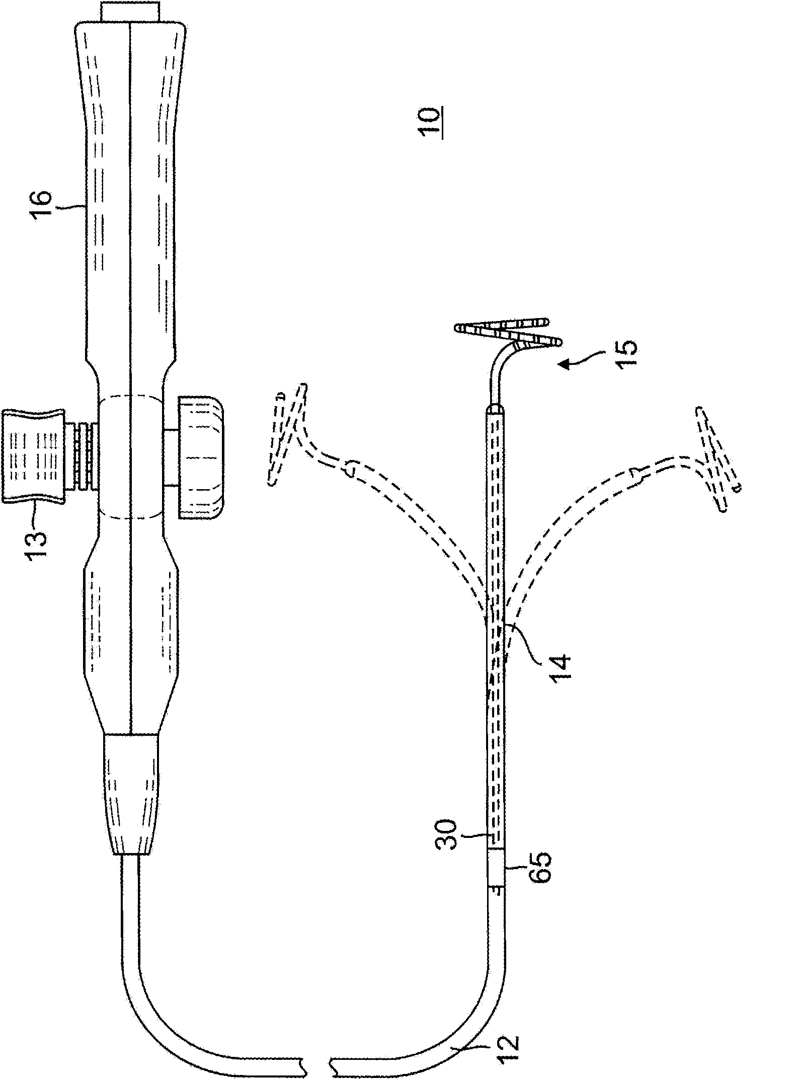
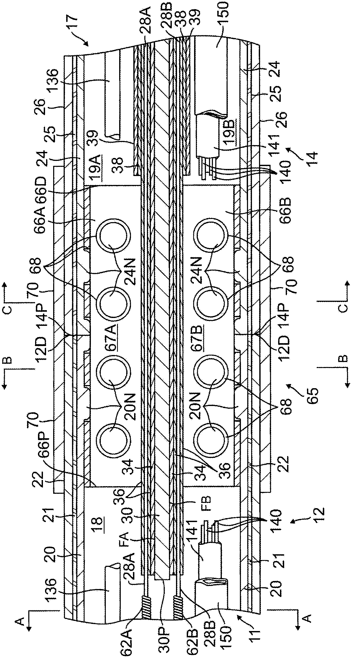
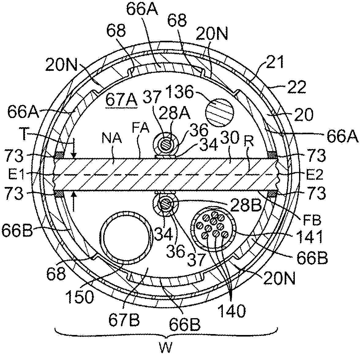
[0027] The present invention relates to a catheter having a catheter body (or shaft) and a deflectable distal portion having an elongated flat beam or "blade" that passes through one or more A fiber-pulling member is deflected to achieve precise in-plane bi-directional deflection. The use of flat beams maximizes the space for components within the catheter, including guide wires, puller wires, cables, tubing, and any other support members for advanced distal tip designs. The use of fibrous puller members avoids breakage and weakening problems associated with puller wires. combine figure 1 A catheter 10 according to an embodiment of the present invention includes a catheter body 12, a deflectable distal section 14 distal to the catheter body, and a control handle 16 proximal to the catheter shaft. The deflectable section 14 has a tip assembly 15 having, for example, a noose design with a generally circular main portion extending from the distal end of the deflectable section ...


PUM


Abstract

A catheter (12) has a metal deflection beam (30) with rectangular cross-section and one or two fiber puller members (28A, 28B) for predictable on-plane bi-directional deflection. Each fiber puller member is anchored at its distal end to a respective surface of the beam by a metal ferrule (31A, 31B) that is crimped onto the distal end. The ferrule is shaped to provide a flat outer underside that can lie flat against a beam surface and a thin planar distal section that is welded to the beam. With a distal end of the beam sandwiched between the thin planar distal section of two ferrules, the ferrules and the beam can be welded together by a single laser pulse.

Description

technical field [0001] The present invention relates to the use of medical devices in the blood vessels of a patient for the purpose of diagnosing or treating the patient, such as mapping tissue and / or ablating tissue using radio frequency (RF) or other energy sources. More particularly, the present invention relates to deflectable catheters having flattened beams for bi-directional deflection in a plane. Background technique [0002] Leads have been commonly used in medical practice for many years. They are used to stimulate and map electrical activity in the heart, and to ablate sites of abnormal electrical activity. In use, the lead is inserted into an introducer sheath that has been positioned within the main vein or aorta (eg, femoral artery) and guided into the ventricle. Intraventricularly, the catheter is extended beyond the distal end of the introducing sheath to expose the mapping assembly. The catheter is manipulated by motion such that the mapping assembly is ...

Claims


Application Information

Patent Timeline
Patent Type & Authority Applications(China)
IPC IPC(8): A61B18/14A61B18/12A61B5/042
CPCA61M25/0152A61M25/0147A61M25/0009A61M2025/015A61M25/0144
Inventor J.吉梅内滋
Owner BIOSENSE WEBSTER (ISRAEL) LTD
Learn More