Paint-spraying rotary frame for motor

A technology of rotating frame and rotating disk, which is applied in the direction of spraying device, etc., which can solve the problems of poor operation safety, low efficiency, and high labor intensity.

Inactive Publication Date: 2014-08-13
SUZHOU CMT AUTOMATION EQUIP
View PDF7 Cites 4 Cited by
  • Summary
  • Abstract
  • Description
  • Claims
  • Application Information

AI Technical Summary

Problems solved by technology

[0003] The technical problem to be solved by the present invention is to solve the problems of high labor intensity, low efficiency and poor operation safety when spraying large motors

Method used


Image

  • Paint-spraying rotary frame for motor
  • Paint-spraying rotary frame for motor
  • Paint-spraying rotary frame for motor

Examples


Embodiment Construction

[0013] The specific implementation manners of the present invention will be further described in detail below in conjunction with the accompanying drawings and embodiments. The following examples are used to illustrate the present invention, but are not intended to limit the scope of the present invention.

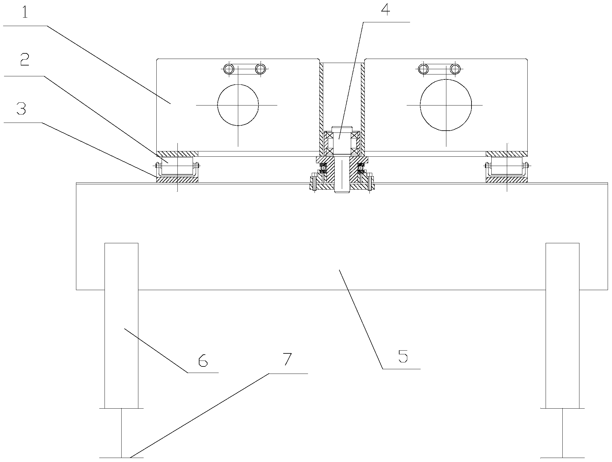
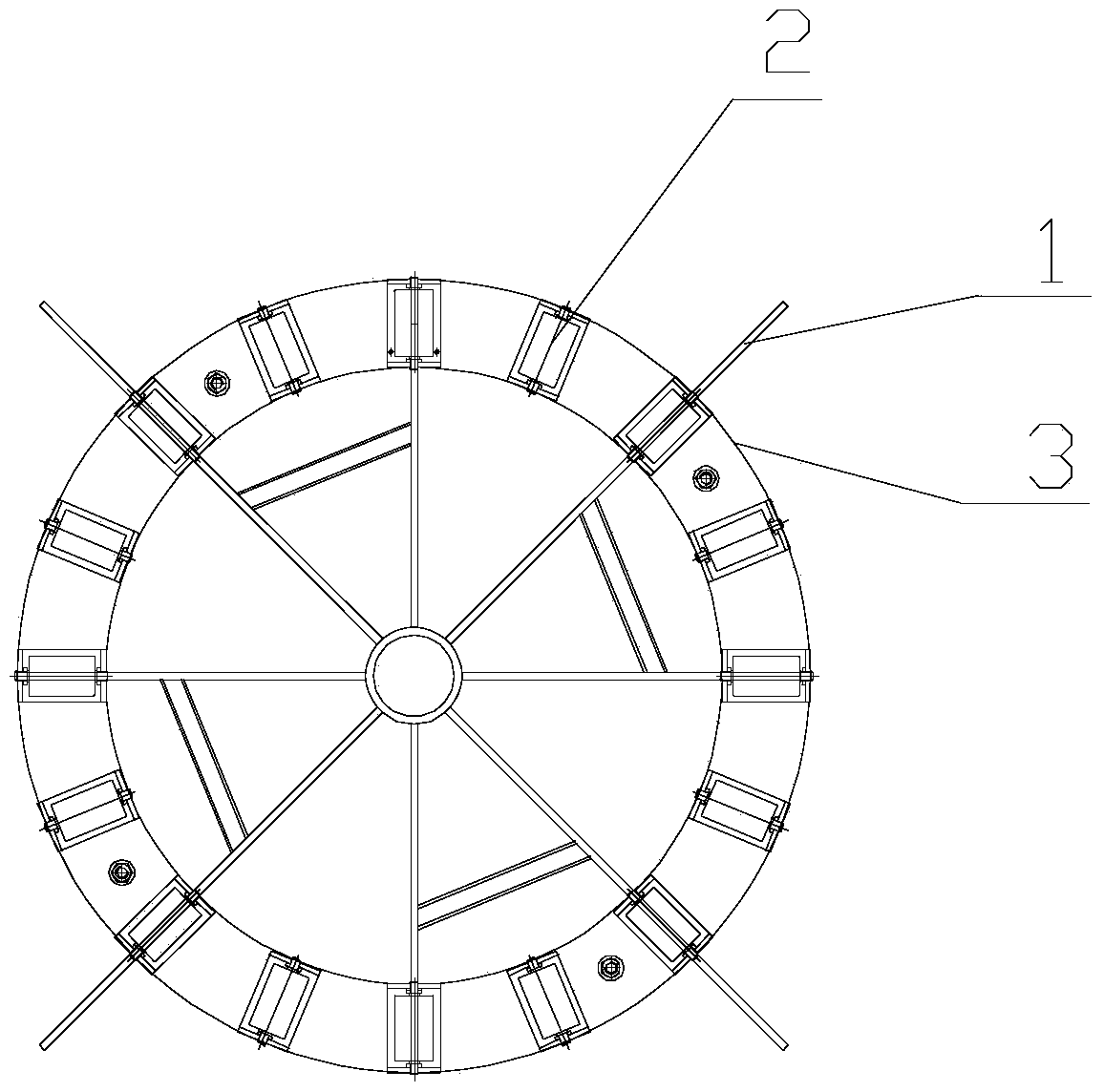
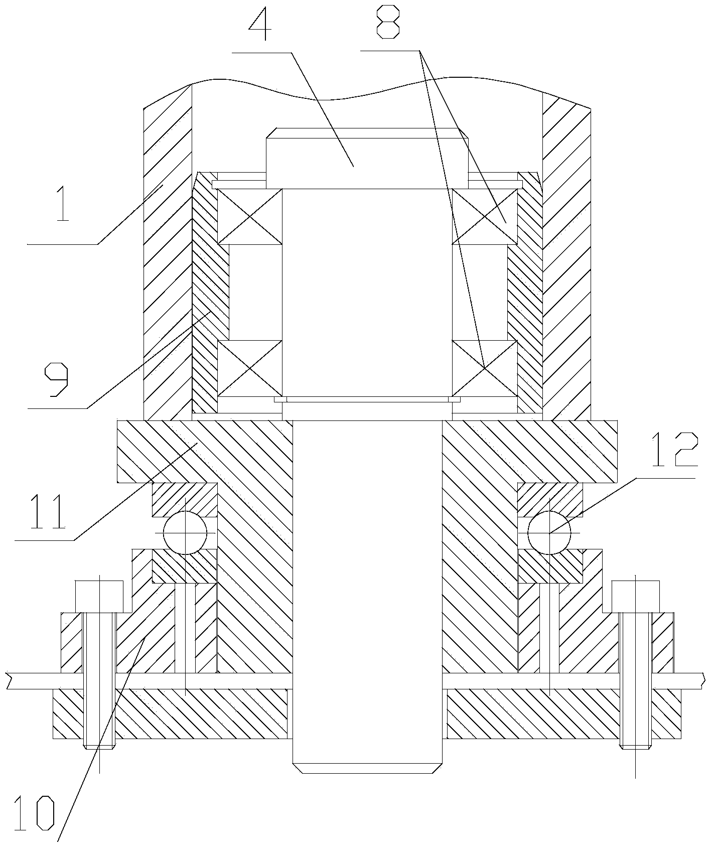
[0014] Such as Figure 1 to Figure 3 The shown motor painting carousel of the present invention includes: a radial rotating disk 1 , a support roller 2 , a support seat plate 3 , a rotating mandrel 4 and a base 5 . There are 16 support rollers 2 (at least 3), and they are evenly distributed in the ring-shaped support seat plate 3 . All support rollers 2 form a plane supporting the radial rotating disk 1 .

[0015] The radial rotating disk 1 is erected on the support roller 2, connected with the base 5 through the rotating mandrel 4, and can rotate freely. The support seat plate 3 is fixedly connected with the base 5 by bolts. The base 5 is a transport plate with a fram...


PUM


Abstract

The invention discloses a paint-spraying rotary frame for a motor. The paint-spraying rotary frame for the motor comprises a radioactive rotating disk, support rollers, a support base plate, a rotary mandrel and a base, wherein at least three support rollers are provided and are arranged in the support base plate respectively; all the support rollers construct a plane for supporting the radioactive rotating disk; the radioactive rotating disk is arranged on the revolving support rollers, is connected with the base through the rotary mandrel, and can rotate freely; the support base plate is fixedly connected with the base; the base has a hollow framework structure, and is used for reserving a space for performing bottom operation. By adopting the paint-spraying rotary frame for the motor, the motor can be rotated to any angle conveniently and easily, and an operator can spray paint onto the entire surface of the motor without moving to other places or moving equipment. When the operator needs to spray paint to the bottom, the paint-spraying rotary frame for the motor can be used for supporting stably, so that the safety of the operator is ensured.

Description

technical field [0001] The invention relates to a motor painting rotating frame. Background technique [0002] To paint a large motor, usually the large motor to be painted is placed on a simple workbench and painted manually. Due to the relatively large size of the large motor, when working on different sides of the machine, the worker needs to move to the corresponding position and at the same time move the working tool. Such operation just seems very strenuous to the sprayer, and sometimes the pipeline of the operation tool is not long enough and will cause more troubles. Painting the bottom of the large motor also brings the above problems, and there are safety hazards, because the large motor needs to be hoisted, and the workers are located below when they are working, which is more dangerous. Contents of the invention [0003] The technical problem to be solved by the present invention is to solve the problems of high labor intensity, low efficiency and poor operat...

Claims


Application Information

Patent Timeline
Patent Type & Authority Applications(China)
IPC IPC(8): B05B13/02
CPCB05B13/0242
Inventor 杨久成
Owner SUZHOU CMT AUTOMATION EQUIP
Why Eureka
Try Eureka