Spiral photoelectric yarn cleaner

A yarn clearer and photoelectric technology, which is applied in the direction of optical testing flaws/defects, textiles and papermaking, etc. It can solve problems such as easy to miss flat yarn flaws, unable to monitor yarn diameter, etc., and achieve the effect of improving the identification rate

Active Publication Date: 2014-08-13
汪建建
View PDF8 Cites 3 Cited by
  • Summary
  • Abstract
  • Description
  • Claims
  • Application Information

AI Technical Summary

Problems solved by technology

[0003] Regardless of whether it is a mechanical yarn clearer or an electronic yarn clearer, the detection index of the yarn is to monitor a certain diameter of the yarn at a fixed angle, and cannot monitor the diameter of the entire yarn. Therefore, it is easy to miss flat yarn defects.

Method used


Image

  • Spiral photoelectric yarn cleaner
  • Spiral photoelectric yarn cleaner
  • Spiral photoelectric yarn cleaner

Examples


Embodiment Construction

[0016] Below in conjunction with accompanying drawing and embodiment the present invention is further described:

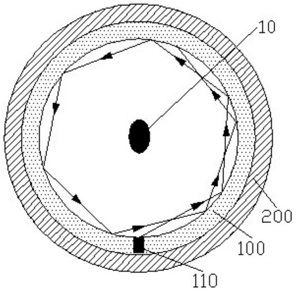
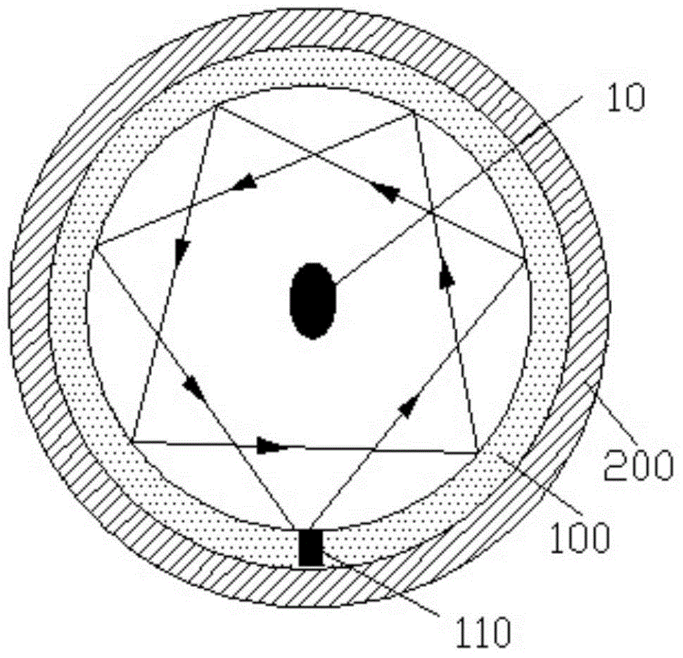
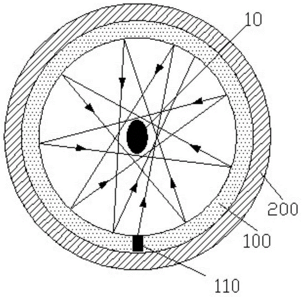
[0017] In this example, see figure 1 , the spiral photoelectric yarn clearer includes a monitoring ring 100 whose inner wall is provided with a reflective coating, the center of the monitoring ring 100 passes through the yarn 10 to be monitored, and the inner wall of the monitoring ring 100 is provided with a 100 is a rotatable optical emitting head 110 on a plane. The monitoring ring 100 is slidably arranged on an annular support 200 and driven to rotate by a driver. The two sides of the plane where the optical emitting head 110 emits light and scans are provided with monitoring devices. An optical monitoring device for emitting light from the optical emitting head 110.

[0018] For the above-mentioned spiral photoelectric yarn clearer, the light received and emitted by the optical monitoring device and the optical emitting head 110 is infrared rays, and the use...


PUM


Abstract

The invention provides a spiral photoelectric yarn cleaner. The spiral photoelectric yarn cleaner comprises a monitoring ring provided with a reflecting coating; a yarn needing to be monitored passes through the center of the monitoring ring; a rotatable optical emission head sweeping over the plane of the monitoring ring is arranged on the inner wall of the monitoring ring; the monitoring ring is slidingly arranged on an annular support and driven to rotate by use of a driver; optical monitoring devices for monitoring light emitted by the optical emission head are arranged at the two sides of the plane over which the light emitted by the optical emission head sweeps. Light emitted by the optical emission head of the spiral photoelectric yarn cleaner is reflected continuously on the inner wall of the monitoring ring so that a similarly circular optical trajectory is formed; when the optical trajectory is blocked by the yarn, the diffuse reflection of the light is formed on the surface of the yarn and monitored by the optical monitoring devices; as the diameter of the yearn is monitored by virtue of the optical trajectory in an annular form, the optical trajectory is applicable to yarn defects of any shapes, and consequently, the discrimination rate of the yarn defects is improved.

Description

Technical field [0001] The invention relates to the field of textile testing equipment, in particular to a photoelectric yarn clearer for monitoring yarn quality. Background technique [0002] Cops produced in the spinning process generally have defects such as slubs, fluff and dust debris, so yarn clearers must be used to inspect and clean the yarns. According to its principle and structure, yarn clearers can be divided into two categories: mechanical and electronic, namely mechanical yarn clearers and electronic yarn clearers. The mechanical yarn clearer is composed of metal blades or comb needles. It can measure the thickness change of the yarn, but it is easy to damage the fiber, shave the yarn, and affect the elasticity of the yarn. Especially, when the sensitivity is increased, it is easy to accumulate floating fibers and dust. Miscellaneous, leading to decapitation. The electronic yarn clearer adopts non-contact detection, which will not damage or shave the yarn. It...

Claims


Application Information

Patent Timeline
Patent Type & Authority Applications(China)
IPC IPC(8): D01H13/32D01H13/14G01N21/88
Inventor 徐强
Owner 汪建建
Why Eureka
Try Eureka