Optical element clamping and angle adjusting mechanism

An optical element and angle adjustment technology, applied in optical elements, optics, instruments, etc., can solve the problems of high cost, complicated processing and assembly, inconvenient operation, etc., and achieve the effect of convenient operation, simple structure and cost reduction.

Active Publication Date: 2014-08-13
SHANGHAI INST OF OPTICS & FINE MECHANICS CHINESE ACAD OF SCI
View PDF7 Cites 9 Cited by
  • Summary
  • Abstract
  • Description
  • Claims
  • Application Information

AI Technical Summary

Problems solved by technology

[0002] In the experiment of optical precision machinery, the optical components are required to have high installation and adjustment accuracy in many occasions. In the past optical machine design, it is generally designed to design an adjustment frame, and the three points of the adjustment frame are in contact with the optical components, and then The disadvantage of this structure is that the centering of the optical element is not good, and the angle of the optical element is not easy to adjust with the top wire structure.
[0003] In the patent document with the publication number CN101369104A, a micro-adjustment device for optical elements is disclosed, which adjusts and positions the optical elements. The advantage of this device is that it has good stability. Adjust and position the optical components, the adjustment accuracy is high, the disadvantage is that the processing and assembly are complicated, the operation is inconvenient, and the cost is high
In the patent document with publication number CN102722016A, a three-degree-of-freedom micro-adjustment mechanism for optical elements Z, tip, and tilt is disclosed. Based on a 3-TPT parallel mechanism, a piezoelectric driver is used as a drive unit, and a flexible kinematic chain is used as a transmission. unit, the capacitive sensor is used as the position detection feedback unit to realize the Z, tip, and tilt three-degree-of-freedom micro-movement of the optical element, which also has the advantage of high adjustment accuracy, but also has the advantages of high cost, complicated processing of the flexible hinge, and poor adjustment of the overall structure. Convenience Disadvantages

Method used


Image

  • Optical element clamping and angle adjusting mechanism
  • Optical element clamping and angle adjusting mechanism
  • Optical element clamping and angle adjusting mechanism

Examples


Embodiment Construction

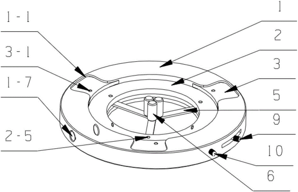
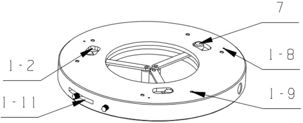
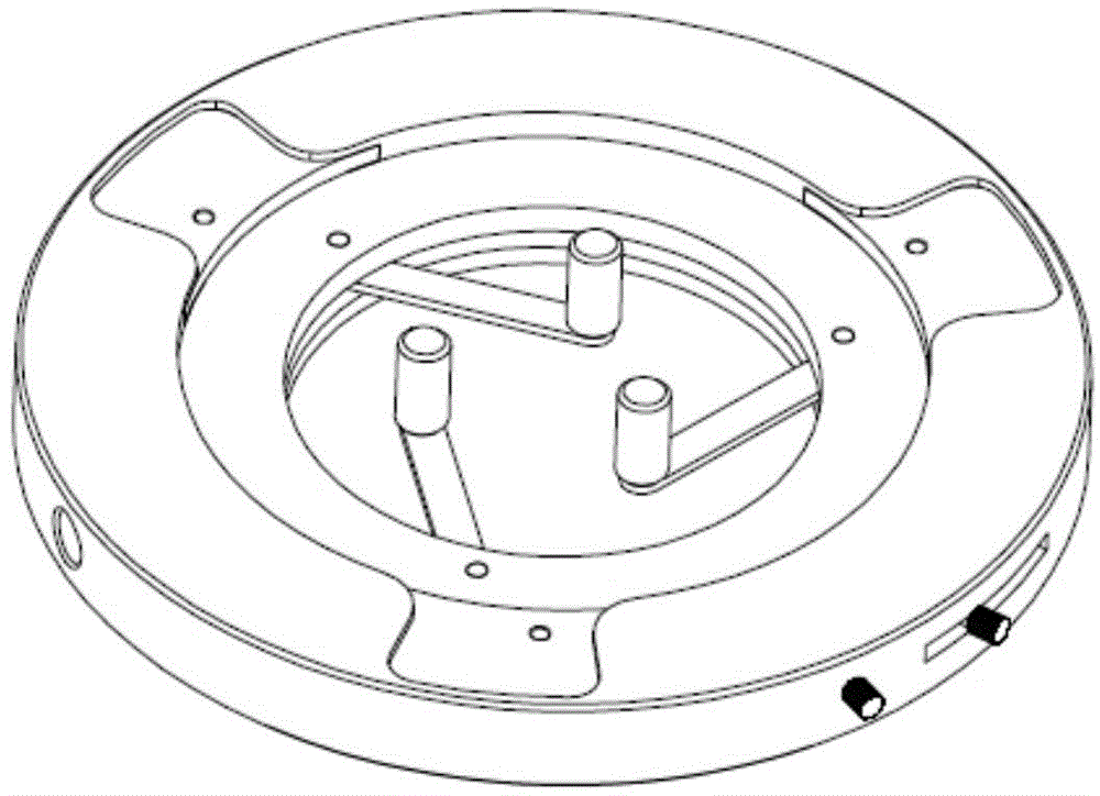
[0042] Below in conjunction with accompanying drawing and embodiment, the present invention will be further described, but should not limit protection scope of the present invention with this:

[0043] like Figure 1-5 As shown, a fixture and angle adjustment mechanism for an optical element includes an outer base 1, an inner top plate 2, a magnetic plate 3, a magnetic block 4, a connecting rod 5, a vertical rod 6, a limit post 7, a magnet 8, and a fixed rod 9 and moving rod 10, such as figure 2 and Figure 6 As shown, the outer base 1 is a cylindrical ring structure, and the top surface of the outer base 1 has three U-shaped grooves 1-1 uniformly distributed at 120 degrees in the circumferential direction, and there is a first reference circle in the middle of the outer base 1 Hole 1-3; the first reference circular hole 1-3 is surrounded by a centrally symmetrical annular step 1-4 and communicates with the U-shaped groove 1-1; the U-shaped groove 1- There is a magnetic pl...


PUM


Abstract

An optical element clamping and angle adjusting mechanism comprises an outer base, an inner top plate, a magnetic plate, one magnet, connection rods, vertical rods, a limiting column, another magnet, a fixed rod and a movable rod. The top plate and a bottom plate rotate relative to each other by adjusting the fixed rod and the movable rod. Under the action of the magnetic plate and the magnets, the top plate keeps in contact with the bottom plate. The three vertical rods are driven to separate through the three connection rods, optical elements of different sizes can be placed, then the rods are reset under the magnetism action of the magnets, the optical elements are clamped among the vertical rods, and accordingly the function of clamping the optical elements of different diameters and sizes is achieved. Due to screw holes in the magnets and a thread screwing mechanism, the vertical rods can move in kidney-shaped limiting through holes in the rear side of the bottom plate, and three-angle adjusting in a plane is achieved. By means of the optical element clamping and angle adjusting mechanism, clamping is achieved through the magnets, a flexible hinge or a spring adjusting mechanism in the prior art is omitted, the structure is simple, and the whole structure is stable, reliable and compact.

Description

technical field [0001] The invention relates to a fixture and an adjustment mechanism, in particular to a fixture and an angle adjustment mechanism of an optical element. Background technique [0002] In the experiment of optical precision machinery, the optical components are required to have high installation and adjustment accuracy in many occasions. In the past optical machine design, it is generally designed to design an adjustment frame, and the three points of the adjustment frame are in contact with the optical components, and then The disadvantage of this structure is that the centering of the optical element is not good, and the angle of the optical element is not easy to adjust with the top wire structure. [0003] In the patent document with the publication number CN101369104A, a micro-adjustment device for optical elements is disclosed, which adjusts and positions the optical elements. The advantage of this device is that it has good stability. The adjustment a...

Claims


Application Information

Patent Timeline
Patent Type & Authority Applications(China)
IPC IPC(8): G02B7/00
Inventor 徐世福王向朝唐锋
Owner SHANGHAI INST OF OPTICS & FINE MECHANICS CHINESE ACAD OF SCI
Why Eureka
Try Eureka