Traffic signal light control method and system based on vehicle queuing length measurement

A technology of traffic signal lights and queue length, applied in the control of traffic signals and other directions, can solve problems such as poor versatility and poor practicability

Inactive Publication Date: 2014-08-13
SOUTHEAST UNIV +1
View PDF5 Cites 35 Cited by
  • Summary
  • Abstract
  • Description
  • Claims
  • Application Information

AI Technical Summary

Problems solved by technology

[0004] For this reason, the technical problem to be solved by the present invention is that in the prior art, it is only possible to calculate the poor versatility and poor practicability caused by the traffic accidents ahead of the fixed detector along the direction of vehicle travel that cause congestion.

Method used


Image

  • Traffic signal light control method and system based on vehicle queuing length measurement
  • Traffic signal light control method and system based on vehicle queuing length measurement
  • Traffic signal light control method and system based on vehicle queuing length measurement

Examples


Embodiment 1

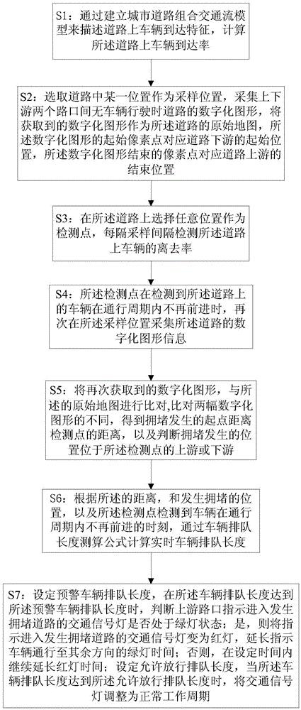
[0062] Such asfigure 1 As shown, as an embodiment of the present invention, the traffic signal light control method based on vehicle queuing length measurement comprises the following steps:

[0063] S1: describe the arrival characteristics of vehicles on the road by establishing a combined traffic flow model on urban roads, calculate the arrival rate of vehicles on the road, and the arrival rate is the number of vehicles entering the road per unit time; further comprising the following steps:

[0064] S11: Divide the combined traffic flow into a steady flow and a discrete flow, the steady flow is composed of continuously entering vehicles passing through the through lane at the upstream intersection, and the discrete flow is composed of vehicles entering the left-turn and right-turn lanes at the upstream intersection, The time when the through lane at the upstream intersection starts to release is set as the cycle start time, and the arrival rate of vehicles on the road is:

...

Embodiment 2

[0075] As an embodiment of the present invention, on the basis of the above-mentioned embodiment 1, the step of comparing the digitized graphics obtained again in the step S5 with the digitized graphics of the original map is specifically: comparing For the different pixels in the two graphics, identify the first different pixel from the downstream to the upstream, which is the location where the congestion occurs.

[0076] Based on the traffic signal control method based on the measurement and calculation of the vehicle queuing length, the digitized graphic information obtained again is compared with the original map, and by comparing the different pixels of the two graphics, it is possible to identify the congestion caused by the occurrence of congestion in the digital graphic. , so as to determine the exact location of the congestion.

Embodiment 3

[0078] As an embodiment of the present invention, on the basis of the above-mentioned embodiment 1 or 2, the step S6 specifically includes the following steps:

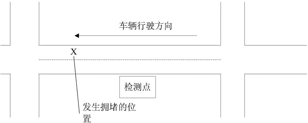
[0079] S61: Judging that the location where the congestion occurs is located upstream or downstream of the detection point; if figure 2 As shown, the location where congestion occurs is located downstream of the detection point.

[0080] S62: If the location where the congestion occurs is located downstream of the detection point, and the vehicle travels from upstream to downstream; the distance between the location where the congestion occurs and the detection point is 1 0 , and the time t when the detection point detects that the vehicle no longer moves forward in the passing period s , then use the vehicle queuing length calculation formula:

[0081] L ( t ) = ( N 1 + ...


PUM


Abstract

The invention provides a traffic signal light control method and system based on vehicle queuing length measurement. Vehicle flow information is divided into steady flow and combined flow by building a city road combined traffic flow model, and actual vehicle flow information can be accurately simulated. Pixel points in an original map of a digital graph can serve as road coordinates by carrying out digital graph collecting on a road, a sampling time interval is set, digital graph information of the road is collected on a sampling position again when it is detected that a vehicle on the road does not move forward any more in a road go-through cycle, a congestion starting position is obtained, a real-time vehicle queuing length can be calculated according to the distance from the congestion starting point to a detection point by means of a vehicle queuing length computational formula, the operation state of an upstream intersection signal light is controlled according to the real-time vehicle queuing length, and accordingly upstream intersection traffic congestion caused due to the fact that the upstream intersection vehicle enters the congested road is avoided.

Description

technical field [0001] The invention relates to a traffic signal light control technology on roads. In particular, it relates to a traffic signal light control method and system based on vehicle queuing length measurement and calculation. Background technique [0002] As the number of vehicles continues to rise, urban roads are increasingly congested, resulting in frequent urban road traffic accidents. Once congestion occurs on the road, it will directly reduce the operating efficiency of the road network and easily induce secondary accidents. An effective way to reduce the negative impact of traffic accidents is to calculate the impact of real-time congestion. According to the calculation, the time when the road reaches the maximum queuing length can be obtained, which provides a reliable theoretical basis for taking effective measures to deal with congestion. [0003] Chinese patent document CN102034354A discloses a method for determining the influence range of urban roa...

Claims


Application Information

Patent Timeline
Patent Type & Authority Applications(China)
IPC IPC(8): G08G1/08
Inventor 顾怀中陆建王锦尧叶坚苏子毅
Owner SOUTHEAST UNIV
Why Eureka
Try Eureka