
Pressure riveting nut automatic feeding device

A technology of riveting nuts and automatic feeding, which is applied in the field of riveting machine parts and can solve problems such as material jams, low work efficiency, and complex structures

Active Publication Date: 2016-08-17
SUZHOU ICOOLMACH EQUIP MFG
View PDF6 Cites 0 Cited by
  • Summary
  • Abstract
  • Description
  • Claims
  • Application Information

AI Technical Summary

Problems solved by technology

In the prior art, people usually put the rivet nut manually into the preset hole of the thin plate, which not only brings hidden dangers to the personal safety of the operator, but also reduces the production efficiency; in addition, there are still Some self-feeding equipment for rivet nuts, but these devices usually have a complex structure, and there are problems such as material jams during the feeding process, and only one rivet nut is sent out in each round of operation, and the work efficiency is still low

Method used

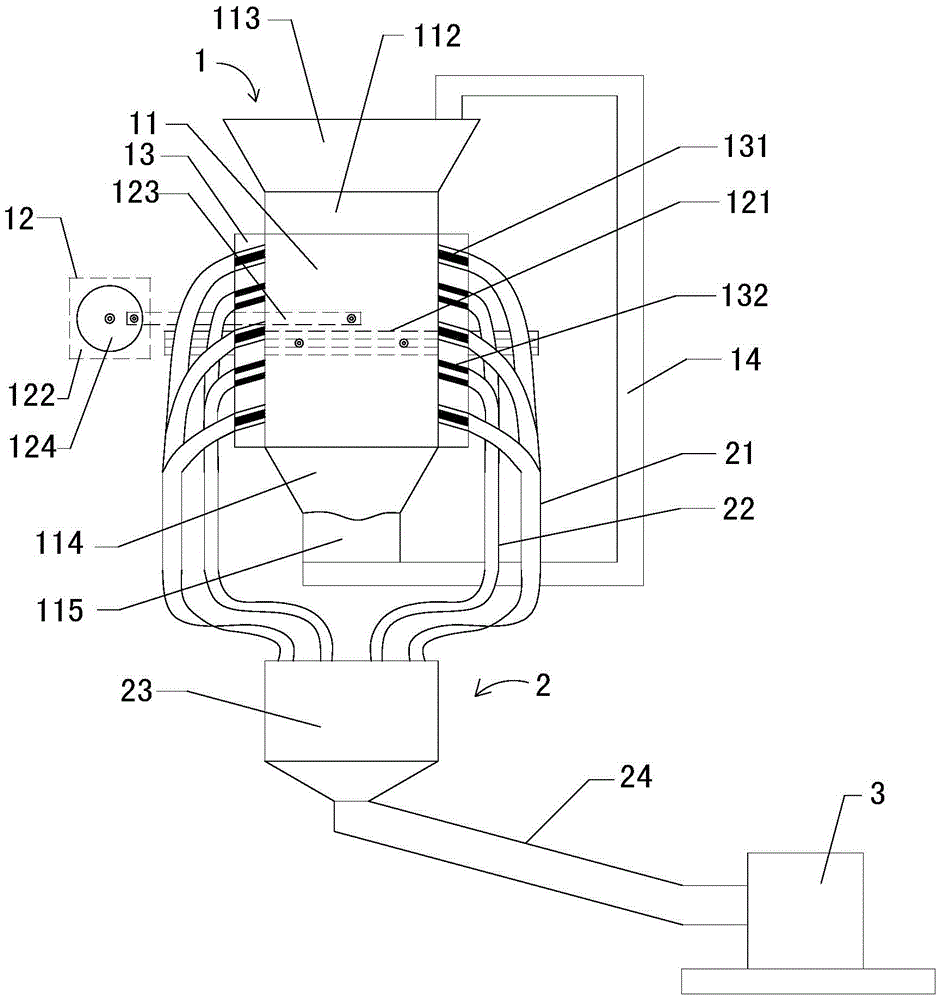

Image

  • Pressure riveting nut automatic feeding device
  • Pressure riveting nut automatic feeding device
  • Pressure riveting nut automatic feeding device

Examples


Embodiment Construction

[0020] The specific implementation manners of the present invention will be further described in detail below in conjunction with the accompanying drawings and embodiments. The following examples are used to illustrate the present invention, but are not intended to limit the scope of the present invention.

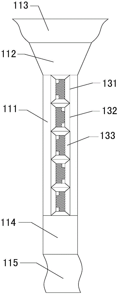
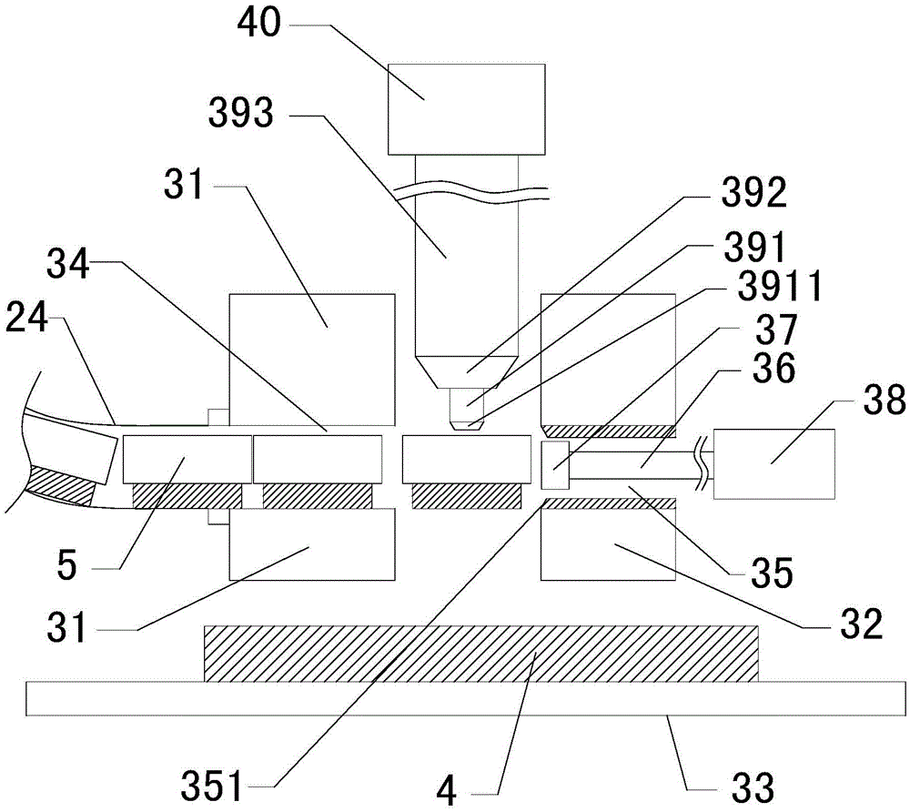
[0021] see Figure 1 to Figure 3 As shown, an automatic feeding device for riveting nuts includes a hopper mechanism 1, a diversion collection mechanism 2 and a riveting mechanism 3; wherein, the hopper mechanism 1 includes a hopper 11, a vibration unit 12, a discharger 13 and a recycling device 14. The vibration unit 12 includes a slide rail 121, a motor 122 and a connecting rod 123. One end of the connecting rod 123 is connected to the output end of the motor 122 through an eccentric wheel 124, and the other end of the connecting rod 123 is connected to the hopper 11 through a rotating shaft. The hopper 11 Reciprocating movement along the left and right directions on th...


PUM


Abstract

The invention relates to an automatic feeding device for a pressing rivet nut. The automatic feeding device for the pressing rivet nut automatically completes the feeding process, meanwhile is simple in structure and high in working efficiency, and does not have the material clamping problem even when working for a long time uninterruptedly. The automatic feeding device for the pressing rivet nut comprises a hopper mechanism, a flow distribution integrating and separating mechanism and a pressing rivet mechanism, wherein the hopper mechanism comprises a hopper, a vibration unit, discharging devices and a circulation material returning device, the vibration unit comprises a sliding rail, a motor and a connecting rod, the discharging devices are in a strip shape and are arranged on the two sides of the hopper respectively, first discharging holes and second discharging holes are alternately formed in the discharging devices in a spaced mode, the circulation material returning device is arranged at the bottom of the hopper, the flow distribution integrating mechanism comprises a first flat guiding tube, a second flat guiding tube, an integrating and separating device and a feeding flat guiding tube, the bottom end of the first flat guiding tube is rotated by 18 degrees and then is communicated with the top end of the integrating and separating device, the bottom end of the second flat guiding tube is communicated with the top end of the integrating and separating device, the top end and the bottom end of the feeding flat guiding tube are communicated with the bottom end of the integrating and separating device and the pressing rivet mechanism respectively, and the pressing rivet mechanism is used for pressing the pressing rivet nut into a reset hole in a workpiece.

Description

technical field [0001] The invention relates to a component of a riveting machine, in particular to an automatic feeding device for a riveting nut. Background technique [0002] The rivet nut is a kind of fastener used in sheet metal, thin plate, chassis, and cabinet. The rivet nut is pressed into the preset hole of the workpiece such as the thin plate by a press, and the periphery of the hole is plastically deformed, so that The rivet nut is tightly fixed on the thin plate, so that an internal thread structure capable of effectively fixing the screw is formed on the thin plate. In the prior art, people usually put the rivet nut manually into the preset hole of the thin plate, which not only brings hidden dangers to the personal safety of the operator, but also reduces the production efficiency; in addition, there are still Some self-feeding equipment for rivet nuts, but these devices usually have a complex structure, and there are problems such as material jams during the ...

Claims


Application Information

Patent Timeline
Patent Type & Authority Patents(China)
IPC IPC(8): B21D39/00B21D43/00
Inventor 徐明
Owner SUZHOU ICOOLMACH EQUIP MFG
Learn More