Three-component mixing head for injection molding

A mixing head and mixed injection technology, which is applied in the field of steering wheel foam molding and three-component mixing head for injection molding, can solve the problems of poor mixing effect, complicated small piston manufacturing process and high product rejection rate.

Active Publication Date: 2014-08-20
TIANHE FUAO AUTO SAFETY SYST CHANGCHUN
View PDF3 Cites 4 Cited by
  • Summary
  • Abstract
  • Description
  • Claims
  • Application Information

AI Technical Summary

Problems solved by technology

[0004] The invention discloses a three-component mixing head for injection molding to solve the problem that in the prior art, the color paste flows out through the corner of the center hole of the small piston color paste injection, and the color paste, ISO, and POL cannot fully collide; the mixing effect is not good, The foaming is not full, easy to produce air holes and dark pits, and the prod

Method used


Image

  • Three-component mixing head for injection molding
  • Three-component mixing head for injection molding
  • Three-component mixing head for injection molding

Examples


Embodiment Construction

[0024] An embodiment of the present invention will be described in detail below in conjunction with the accompanying drawings.

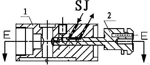
[0025] Examples of the present invention Figure 7 , Figure 8 , Figure 9 , Figure 10 As shown, it includes a pressure regulating core block 1 and a small piston 2.

[0026] Such as Figure 9 , Figure 10 , Figure 11 As shown, the pressure regulating core block 1 includes a small piston push rod installation hole, color paste input hole 1a, color paste output hole 1b, ISO input hole 1c, ISO output hole 1d, POL input hole 1e, POL output hole 1f, horizontal The mixed injection area 1g, the mixed material output hole 1h; there is an included angle of 60° between the color paste input hole 1a and the horizontal mixed injection area 1g.

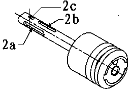
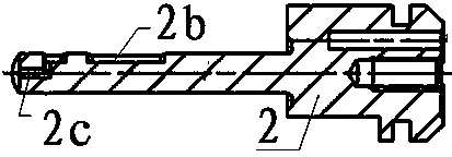
[0027] Such as Figure 8 As shown, the push rod of the small piston 2 has a symmetrical high-pressure circulation tank 2a and a color paste circulation tank 2b; the color paste circulation tank 2b is located o...


PUM


Abstract

The invention discloses a three-component mixing head for injection molding. The mixing head comprises a pressure regulating core block and a small piston. The pressure regulating core block comprises a small piston push rod installing hole, a color paste feeding hole, a color paste discharging hole, an ISO feeding hole, an ISO discharging hole, a POL feeding hole, a POL discharging hole, a horizontal mixing and injecting zone and a mixture discharging. An included angle is formed between the color paste feeding hole and the horizontal mixing and injecting zone. The push rod of the small piston is provided with a first high pressure circulating groove, a second high pressure circulating groove and a color paste circulating groove, wherein the first high pressure circulating groove and the second high pressure circulating groove are symmetrically arranged, and the color paste circulating groove is located on the symmetrical center line of the first high pressure circulating groove and the second high pressure circulating groove. The push rod of the small piston is slidably mounted in the small piston push rod installing hole in the pressure regulating core block through clearance fit and can carry out linear reciprocating motion along the small piston push rod installing hole. The three-component mixing head has the following advantages: sufficient bumping of three components is realized, a good mixing effect is obtained; ISO and POL do not flow backward relative to the center hole of the small piston during pouring, the color paste injection center hole of the small piston does not have obstruction fault, production efficiency is improved, processing time and maintenance time are saved, and cost for spare parts is reduced.

Description

technical field [0001] The invention belongs to the technical field of foam molding tooling, and relates to a three-component mixing head for injection molding; it is especially suitable for the foam molding manufacture of steering wheels. Background technique [0002] Foam molding focuses on avoiding defects such as underfullness, pores, and dark pits. It has always been a technical topic for engineers and technicians to explore and research in this field; in the past, engineers and technicians researched and explored more on the material (chemical raw material) formula and technical parameters. . [0003] The mixing heads manufactured by foam molding include two-component mixing heads, three-component mixing heads, four-component mixing heads, six-component mixing heads, etc. Such as figure 1 , figure 2 , image 3 , Figure 4 , Figure 5 , Figure 6 As shown, the existing three-component mixing head includes a pressure regulating core block and a small piston; the ...

Claims


Application Information

Patent Timeline
IPC IPC(8): B29C44/34
Inventor 曹震桑健朱靖民
Owner TIANHE FUAO AUTO SAFETY SYST CHANGCHUN
Why Eureka
Try Eureka