A condensation type yarn breaking protection device

A protection device and condensation-type technology, applied in textiles, textiles, papermaking, looms, etc., can solve the problems of secondary accidents, losses, etc., and achieve the effect of preventing yarn disorder.

Inactive Publication Date: 2016-06-01
吴江茂春喷织服饰有限公司
View PDF9 Cites 0 Cited by
  • Summary
  • Abstract
  • Description
  • Claims
  • Application Information

AI Technical Summary

Problems solved by technology

[0003] In the traditional yarn transmission process, the elastic pressure wheel is generally used to tighten the yarn to keep the straightness of the yarn transmission track. However, once the yarn breaks, the yarn will pop up and wind other parts of the loom, and then It is very easy to cause secondary accidents and cause greater losses

Method used


Image

  • A condensation type yarn breaking protection device
  • A condensation type yarn breaking protection device

Examples


Embodiment Construction

[0015] Below in conjunction with accompanying drawing and embodiment the present invention is further described:

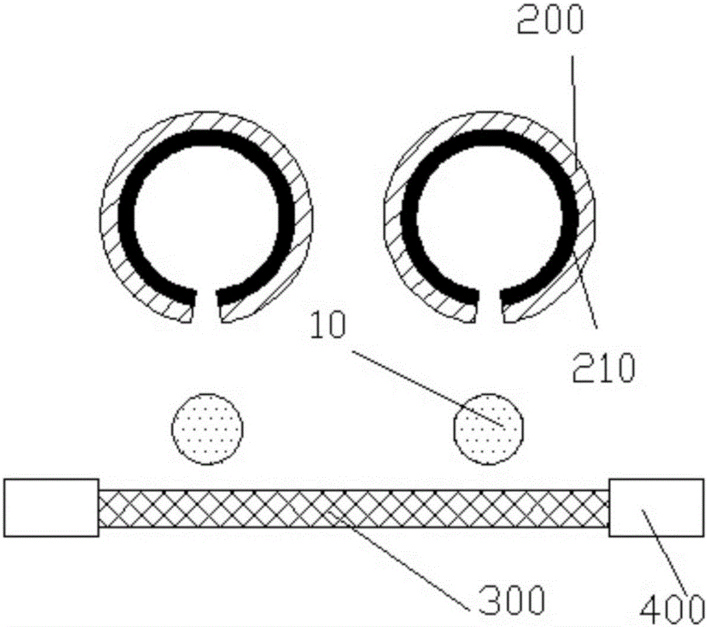
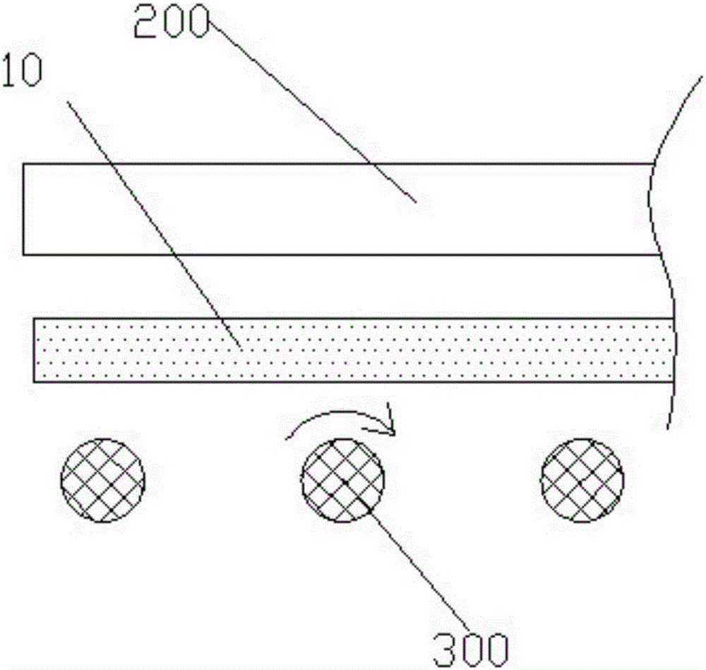
[0016] In this example, see figure 1 and figure 2 , the condensation-type broken yarn protection device includes an atomizing device and a condensation plane, the atomization device and the condensation plane are respectively arranged on both sides of the transmission path of the yarn 10, and the water mist sprayed by the atomization device covers the yarn 10 The transmission path, the condensation plane includes a refrigeration device 400 providing a cold source.

[0017] In the above-mentioned condensation-type broken yarn protection device, the condensation plane is composed of heat-conducting wires 300 arranged parallel to each other at intervals, the heat-conducting wires 300 are perpendicular to the transmission path of the yarn 10, and the refrigeration device 400 is arranged At one end or both ends of the wire 300 , the condensation plane formed by the ...


PUM


Abstract

The invention provides a condensation type yarn-breaking protecting device which comprises an atomization device and a condensation plane. The atomization device and the condensation plane are arranged on the two sides of a yarn conveying route respectively. Water mist sprayed by the atomization device covers the yarn conveying route. The condensation plane comprises a cooling device which provides a cold source. The water mist sprayed by the atomization device stains yarn and blows the yarn to the condensation plane, the yarn is condensed on the condensation plane, and jumping around of the yarn is effectively avoided.

Description

Technical field [0001] The invention relates to the field of textile machinery and equipment, in particular to a condensation type yarn breakage protection device. Background technique [0002] The looms are all equipped with a warp break self-stop device, the purpose of which is to detect warp break and send a stop signal. Their types: photoelectric (far-infrared detection), stop-and-go rack, carding and rotating. At present, the stop frame type is mostly used, and its working principle: the stop frame is installed between the back beam and the heald frame, and there are several rows of stop bars on it. The warp stop strip is a combination of inner and outer conductors separated by a thick plastic film to form an open circuit. Many warp stop pieces are set on the warp stop strip, and each warp yarn passes through a warp stop piece alone. When the loom is running, the warp yarn tension will pull up the warp stop piece so that it does not contact with the inner conductor of...

Claims


Application Information

Patent Timeline
Patent Type & Authority Patents(China)
IPC IPC(8): D03D51/20D03D49/00
Inventor 钟钊伟
Owner 吴江茂春喷织服饰有限公司
Why Eureka
Try Eureka