Grinding device for powder photocatalytic material

A technology of photocatalytic materials and powder grinding, which is applied in the fields of application, chemical instruments and methods, cleaning methods and appliances, etc. It can solve the problems of uneven grinding parts, the failure of ground materials, and the reduction of the powder output rate of the device. Increase the service life, prevent clogging, and prevent the effect of air flow disorder

Active Publication Date: 2022-02-11
YANCHENG INST OF TECH
View PDF7 Cites 0 Cited by
  • Summary
  • Abstract
  • Description
  • Claims
  • Application Information

AI Technical Summary

Problems solved by technology

[0004] The purpose of the present invention is to provide a milling device for powder photocatalytic materials to solve the problem that some grinding parts of the milling device proposed in the background art are uneven and directly contact with the ground material, which may easily cause the ground material to be ground. It will not come off the grinding parts, resulting in a reduction in the powder output rate of the device, and in the long run it will block the device and cause damage to the device

Method used


Image

  • Grinding device for powder photocatalytic material
  • Grinding device for powder photocatalytic material
  • Grinding device for powder photocatalytic material

Examples


Embodiment Construction

[0024] Next, the technical solutions in the embodiments of the present invention will be described in connection with the drawings of the embodiments of the present invention, and it is understood that the described embodiments are merely the embodiments of the present invention, not all of the embodiments.

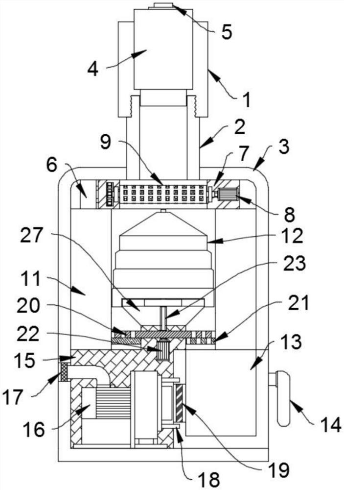
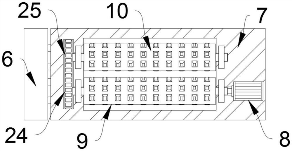
[0025] See Figure 1-5 In one embodiment of the present invention, an example of a grinding apparatus for a powder photocatalytic material comprising a main body housing 3, an internal portion of the main body housing 3 having a primary grinding block 7, and a primary grinding block 7 The main body housing 3 is slidably connected by the jitter cylinder 6, and after the propulsion cylinder 4 completely pushes the photocatalytic material through the first coarse mill 9 and the second coarse grinding roller 10, the jitter cylinder 6 starts to drive the primary grinding block 7 and the interior The component is turned back and forth, thereby separating the photocatalytic material ...


PUM


Abstract

The invention discloses a grinding device for a powder photocatalytic material, relates to the technical field of powder photocatalytic material grinding, and aims to solve the problems that some grinding parts of a grinding device in the prior art are uneven and are in direct contact with a ground material, so that the ground material cannot fall off the grinding parts, the powder yield of the device is reduced; and the device can be blocked and damaged for a long time. A first-stage grinding block is arranged in a body shell and is in sliding connection with the body shell through a shaking air cylinder, a second-stage grinding block is arranged at the bottom of the first-stage grinding block, a grinding column is arranged on the inner side of the second-stage grinding block, a third-stage grinding block is arranged at the bottom of the second-stage grinding block, an air exhaust motor is arranged in the third-stage grinding block, a collecting frame is arranged on one side of the third-stage grinding block, and the collecting frame is slidably connected with the body shell through a sliding groove.

Description

Technical field [0001] The present invention relates to the field of polishing technology of the powder photocatalytic material, and is specifically a abrasion apparatus for a powder photocatalytic material. Background technique [0002] The photocatalytic material refers to a class of semiconductor catalyst materials required for photochemical reactions that occur under the action of light, and there are many photocatalytic materials, including titanium dioxide, zinc oxide, tin oxide, zirconia. A variety of oxide sulfide semiconductors such as cadfium sulfide, wherein titanium dioxide is strong and non-toxic, which is the world's most red nano-photocatalyst material. [0003] However, the existing grinding apparatus has some grinding components unevenness and is in direct contact with the abrasive material, which is easy to cause the abrasive material to be can't be grounded, resulting in a decrease in the discharge rate of the apparatus, and it is conventional clogging device. ...

Claims


Application Information

Patent Timeline
Patent Type & Authority Applications(China)
IPC IPC(8): B02C4/08B02C4/42B02C19/00B02C7/08B02C21/00B08B15/04
CPCB02C4/08B02C4/42B02C19/00B02C7/08B02C21/00B08B15/04
Inventor 张蓓蓓奚新国刘超董鹏玉陈小卫王勿忧
Owner YANCHENG INST OF TECH
Why Eureka
Try Eureka