
diesel pile hammer

A piling hammer and diesel technology, applied in sheet pile wall, construction, infrastructure engineering and other directions, can solve the problem of undesired pendulum

Inactive Publication Date: 2017-09-12
UTM UNIVERSAL TIEFBAU MASCH VERW & BET GES MBH
View PDF4 Cites 0 Cited by
  • Summary
  • Abstract
  • Description
  • Claims
  • Application Information

AI Technical Summary

Problems solved by technology

In addition, undesired swinging into the

Method used


Image

  • diesel pile hammer
  • diesel pile hammer
  • diesel pile hammer

Examples


Embodiment Construction

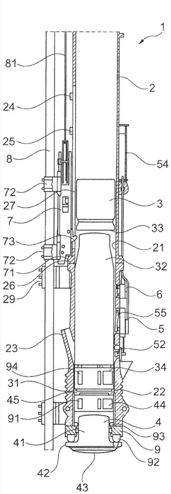
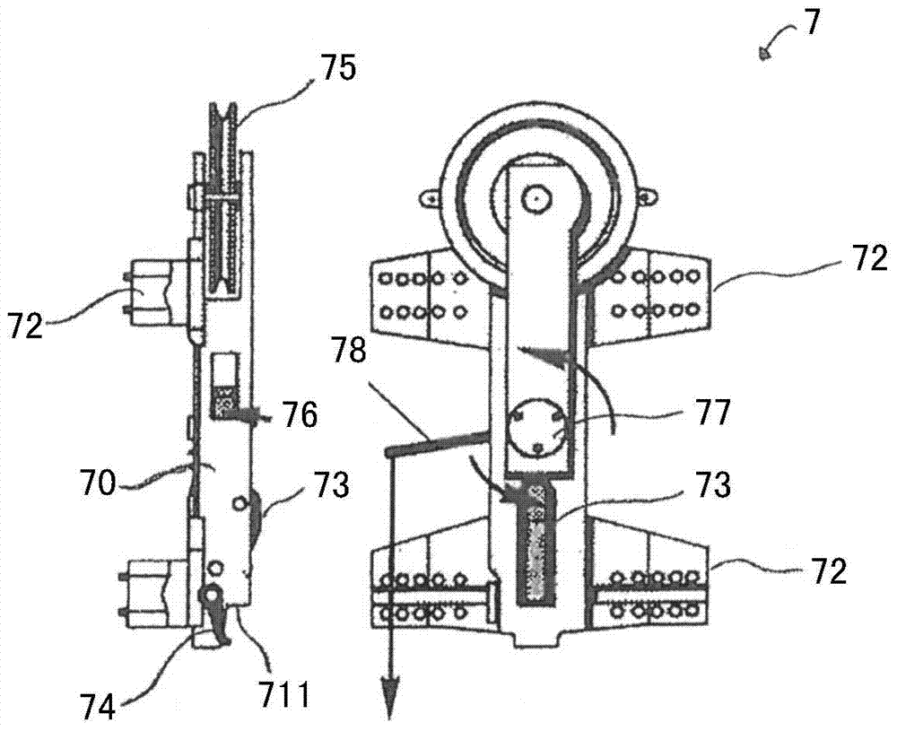
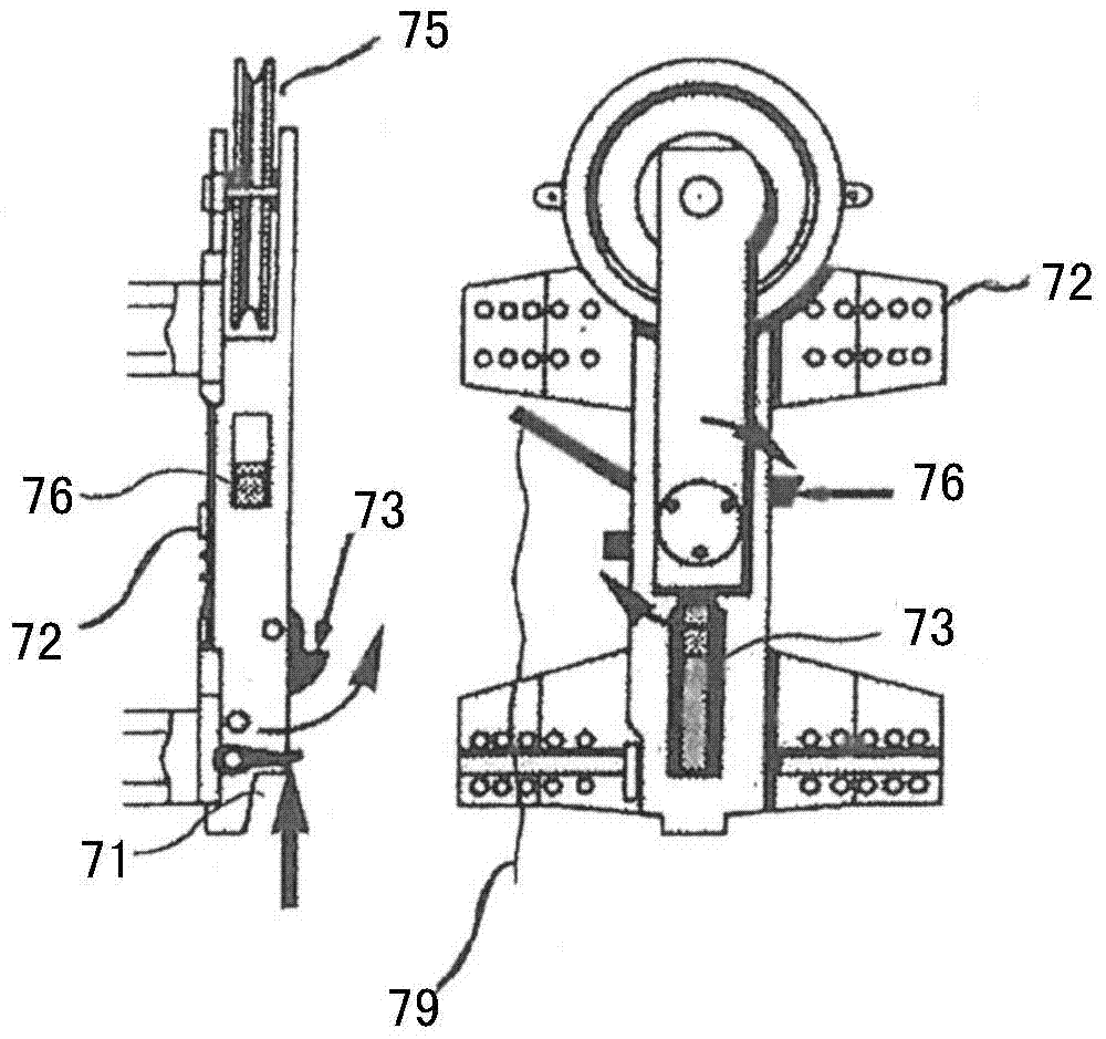
[0022] The piling device chosen as an example comprises a diesel piling hammer with a cylinder 2 open on both sides, which can often have a length of 5 to 10 meters and a diameter of 0.2 to 1 meter. A piston 3 is movably arranged in the cylinder 2 . A coaxial striker 4 is movably inserted into the open lower end of the cylinder 2 . Fastened to the lower end of the cylinder 2 is an annular bearing unit 9 in which a central rod section 41 of the striker 4 is guided in a sealing and displaceable manner, which rod section has a relative The inner diameter of the cylinder 2 is reduced to the outer diameter.

[0023] On the lower end of the rod section 41 is formed a strike plate 42 below the cylinder 2 , the lower, outwardly directed lower boundary surface 43 of the strike plate, in operation, is in contact with the pile driver to be driven in. The upper ends of the joints work together.

[0024] At the upper end of the rod section 41 of the striker 4 , a piston section 44 is fo...


PUM


Abstract

The ram assembly has a driver (73) which is arranged in piston rear portion and inserted into cylinder groove in diesel ram (1). A lower latching cam (26) is arranged at cylinder. A release mechanism (7) is provided with a control lever which moves the driver into cylinder space by collision with latching cam, and a releasing cam (25) is arranged at cylinder above latching cam to move the driver out from cylinder space by collision with control lever. The latching cam and the control lever are arranged such that the latching cam or control lever is moved out from collision region.

Description

technical field [0001] The invention relates to a piling device according to the preamble of claim 1, comprising a diesel piling hammer with a cylinder, a piston guided movably in the cylinder and a release device and a striker movably guided in the cylinder. Background technique [0002] with also denoted diesel hammer or diesel hammer The piling device of the diesel piling hammer is used especially in foundation work in the construction industry for ramming piles of all types, such as cement columns, iron bearing members, steel sheet piles or the like, into foundations. [0003] In order to start such a diesel piling hammer, the piston is pulled upwards inside the cylinder by means of a release device and released at a certain height, whereby the piston falls under the force of gravity to the striker superior. When falling, the piston is used to actuate the fuel pump through which the fuel, in particular diesel fuel, is supplied. By the falling piston, the air in th...

Claims


Application Information

Patent Timeline
Patent Type & Authority Patents(China)
IPC IPC(8): E02D7/08
CPCE02D7/12
Inventor M·海歇尔
Owner UTM UNIVERSAL TIEFBAU MASCH VERW & BET GES MBH
Learn More