A method and device for on-line monitoring of forced oscillation source in power system

A forced oscillation and power system technology, applied in the field of online monitoring of forced oscillation sources, can solve problems such as low reliability, complex analysis, and imprecise theoretical basis, so as to achieve simple and effective schemes, reduce complexity, avoid analysis errors and be reliable sex-reducing effect

Inactive Publication Date: 2016-12-07
STATE GRID CORP OF CHINA +1
View PDF6 Cites 0 Cited by
  • Summary
  • Abstract
  • Description
  • Claims
  • Application Information

AI Technical Summary

Problems solved by technology

These studies either use an oversimplified stand-alone infinite model, or rely on the real-time model of the entire interconnected grid and the operation data of the entire network. The analysis is very complicated, the theoretical basis is not strict, and the reliability in practical application is low.

Method used


Image

  • A method and device for on-line monitoring of forced oscillation source in power system
  • A method and device for on-line monitoring of forced oscillation source in power system
  • A method and device for on-line monitoring of forced oscillation source in power system

Examples


specific Embodiment 1

[0072] A power plant 3# generator power oscillation occurred. Figure 6 ~ Figure 9 The curves of unit active power, regulation stage pressure, main excitation current and unit frequency are given respectively.

[0073] Through frequency spectrum analysis of the active power and frequency data of 9 steady-state oscillation cycles from 8:32:00 to 8:32:05:595, the oscillation frequency is 1.512Hz. Other analysis results are shown in Table 1.

[0074] Table 1 Frequency, electrical power, excitation current, regulator stage pressure oscillation phasor analysis results

[0075]

[0076] The inertial time constant of the unit is T J =2H=5.349s. The rated capacity of the unit is S aB =200 / 0.85=253.3MVA, rated frequency f B = 50Hz. Can be calculated as:

[0077]The per unit value of the speed fluctuation is: Δω=Δf=0.0503 / 50=0.001006

[0078] The per unit value of power fluctuation is: ΔP e = 41.4648 / 253.3 = 0.1762

[0079] The calculation result of the fluctuating phasor o...

specific Embodiment 2

[0086] In this specific embodiment, the actual measurement data of the 1# machine (non-excitation current monitoring) of the B power plant is analyzed when responding to the grid oscillation.

[0087] Figure 11 and Figure 12 The curves of unit active power and unit frequency are given respectively.

[0088] By analyzing the data of 9 oscillation cycles from 21:02:00 to 21:02:15:640, the oscillation frequency is 0.575Hz. Other analysis results are shown in Table 2.

[0089] Table 2 Frequency and electrical power oscillation phasor analysis results

[0090]

[0091] The inertial time constant of the unit is T J =2H=7.427s. The rated capacity of the unit is S aB =600 / 0.9=666.7MVA, rated frequency f B = 50Hz. Can be calculated as:

[0092] The per unit value of the speed fluctuation is: Δω=Δf=0.0831 / 50=0.001662

[0093] The per unit value of power fluctuation is: ΔP e = 35.8551 / 666.7 = 0.0538

[0094] The calculation result of the fluctuating phasor of the mechani...


PUM


Abstract

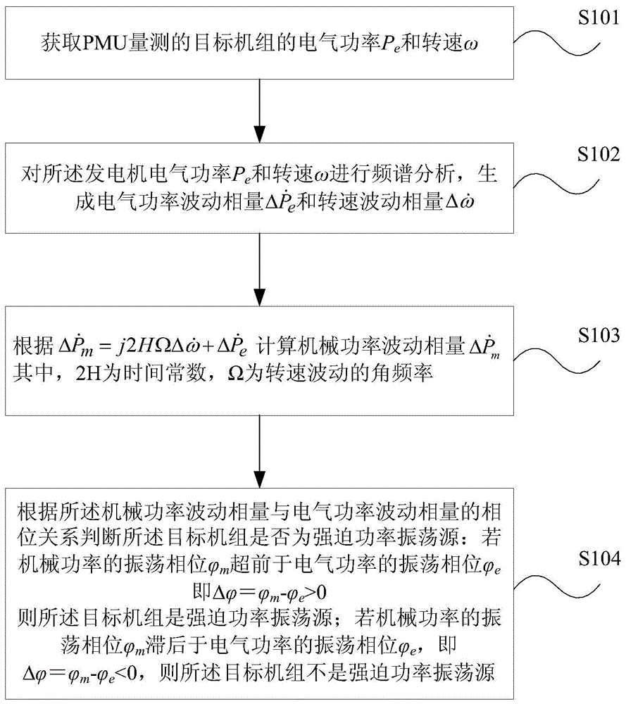
The invention provides an online monitoring method of a forced oscillation source of an electric power system. The method includes the steps that the electric power Pe and the rotating speed omega of a target unit are obtained, wherein the electric power Pe and the rotating speed omega of the target unit are measured by a PMU; spectral analysis is conducted on the electric power Pe and the rotating speed omega of the generator to generate an electric power oscillation phasor and a rotating speed oscillation phasor, and a mechanical power oscillation phasor is calculated according to the formula (please see the formula in the specification), wherein the 2H is a time constant and the capital omega is the angular frequency of rotating speed oscillation; whether the target unit is a forced power oscillation source or not is judged according to the phase relation of the mechanical power oscillation phasor and the electric power oscillation phasor; if a mechanical power oscillation phase phi m is ahead of an electric power oscillation phase phi e, the target unit is the forced power oscillation source; if the mechanical power oscillation phase phi m is behind the electric power oscillation phase phi e, the target unit is not the forced power oscillation source. According to the method, influences on the unit of an external power system are truly reflected, analysis errors caused due to the fact that a whole-network model is introduced are avoided, and the complexity is lowered.

Description

technical field [0001] The invention relates to the field of on-line detection of power systems, in particular to a method and device for on-line monitoring of forced oscillation sources in power systems. Background technique [0002] When the frequency of the power system subjected to continuous periodic power disturbance is close to the natural frequency of system power oscillation, large power oscillation will be caused. The response caused by the disturbance is not only related to the characteristics of the power system itself, but also related to the change law of the disturbance. This is called a forced power oscillation. The theory of forced oscillation has a good explanation for some low-frequency oscillation events of non-negative damping mechanism that actually occur, and is more and more recognized by experts and scholars at home and abroad, and the research on the mechanism of forced power oscillation is also attracting more and more attention. [0003] Since th...

Claims


Application Information

Patent Timeline
Patent Type & Authority Patents(China)
IPC IPC(8): G01R31/00
Inventor 王茂海牛四清张哲刘之滨齐霞司佳伟
Owner STATE GRID CORP OF CHINA
Why Eureka
Try Eureka