Electromagnetic Bearingless Doubly Salient Motor and Its Control Method

A technology of a doubly salient motor and a control method, which is applied to electrical components, holding devices using magnetic attraction or thrust, etc., can solve the problems of high-speed and stable operation of bearingless motors, reliance on more power devices, and motor performance degradation, etc. Achieve the effect of reducing suspension control power devices, simple system structure, and simplified structure

Active Publication Date: 2018-01-05
NANJING UNIV OF AERONAUTICS & ASTRONAUTICS
View PDF6 Cites 0 Cited by
  • Summary
  • Abstract
  • Description
  • Claims
  • Application Information

AI Technical Summary

Problems solved by technology

[0005] The technical problem to be solved by the present invention is to provide an electromagnetic bearingless double-salient pole motor and its control method in view of the deficiencies of the above-mentioned background technology. The motor uses the excitation winding wound on the stator pole to realize the excitation of the motor without the permanent magnet To simplify the structure and provide a bias magnetic field at the same time, the levitation force is controlled by an independent levitation winding to avoid nonlinear coupling problems. The mutual decoupling between them solves the technical problems that the existing bearingless motors are difficult to run stably at high speed, the demagnetization of the permanent magnets leads to the performance degradation of the motors, and the coupling of excitation and suspension control leads to complex control methods and relies on more power devices.

Method used


Image

  • Electromagnetic Bearingless Doubly Salient Motor and Its Control Method
  • Electromagnetic Bearingless Doubly Salient Motor and Its Control Method
  • Electromagnetic Bearingless Doubly Salient Motor and Its Control Method

Examples


Embodiment Construction

[0032] Embodiments of the present invention will be described in detail below, and the embodiments described below with reference to the accompanying drawings are exemplary, and are only used to explain the present invention, and cannot be construed as limiting the present invention.

[0033] Those skilled in the art will understand that unless otherwise stated, the singular forms "a", "an", "said" and "the" used herein may also include plural forms. It should be further understood that the word "comprising" used in the description of the present invention refers to the presence of said features, integers, steps, operations, elements and / or components, but does not exclude the presence or addition of one or more other features, Integers, steps, operations, elements, components, and / or combinations thereof. It will be understood that when an element is referred to as being "connected" or "coupled" to another element, it can be directly connected or coupled to the other element ...


PUM


Abstract

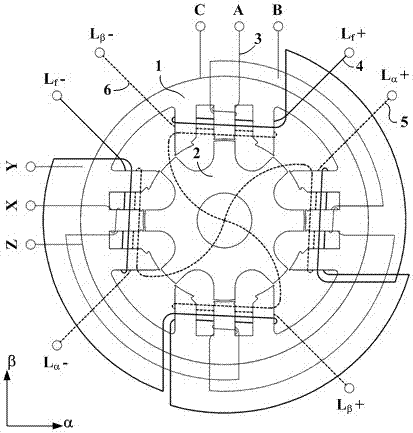
The invention discloses an electromagnetic bearingless double salient pole motor and a control method thereof, belonging to the technical field of bearingless motors. The motor includes: stator core, rotor core, armature winding, excitation winding, suspension winding, the rotor core includes several rotor tooth poles, the stator core includes several stator poles composed of several stator tooth poles, and the space between adjacent stator poles The gap forms a stator slot. The armature coils wound on the stator tooth poles are connected according to the same principle of the change of the magnetic flux of the turn linkage to form an armature winding. The stator slots are embedded with excitation coils and suspension coils wound on the stator poles. The excitation coils wound on each stator pole are connected in sequence to form an excitation winding, and the suspension coils at radially opposite positions in space are connected to form a suspension winding in the α-axis direction and a suspension winding in the β-axis direction to generate an orthogonal suspension magnetic field respectively. The levitation force is controlled by an independent levitation winding to avoid the nonlinear coupling problem, and the levitation current and the excitation current are controlled separately to realize mutual decoupling between the motor output and the levitation.

Description

technical field [0001] The invention discloses an electromagnetic bearingless double salient pole motor and a control method thereof, belonging to the technical field of bearingless salient pole motors. Background technique [0002] The stator and rotor of the switched reluctance motor are salient pole structures, the stator is wound with a concentrated winding, and the rotor has neither permanent magnets nor windings. The structure is simple and firm, and it is easy to maintain. Therefore, the switched reluctance motor has high-temperature environment and high-speed operation adaptability. However, high speed will inevitably cause problems such as heating and wear of mechanical bearings, shorten the life of bearings, affect the normal operation of the motor, reduce the reliability of the system, and greatly weaken the advantages of reluctance motors suitable for high-speed operation. [0003] Compared with mechanical bearings, magnetic bearings can realize the non-contact ...

Claims


Application Information

Patent Timeline
Patent Type & Authority Patents(China)
IPC IPC(8): H02N15/00
Inventor 于立张卓然王雨婷严仰光
Owner NANJING UNIV OF AERONAUTICS & ASTRONAUTICS
Why Eureka
Try Eureka