Touch screen and display device

A touch screen and touch electrode technology, which is applied in instruments, computing, electrical and digital data processing, etc., to achieve the effect of enhancing the touch display effect, improving the display effect and ensuring the picture quality

Active Publication Date: 2014-08-20
BOE TECH GRP CO LTD +1
View PDF3 Cites 14 Cited by
  • Summary
  • Abstract
  • Description
  • Claims
  • Application Information

AI Technical Summary

Problems solved by technology

The touch screen can prevent the touch electrode plate of any pattern from being seen by human eyes when displayed, thereby ensuring the picture quality when the touch screen is displayed, which solves the problem of the touch electrode plate in the touch screen disappearing, and improves the touch screen. The display effect of

Method used


Image

  • Touch screen and display device
  • Touch screen and display device
  • Touch screen and display device

Examples


Embodiment 1

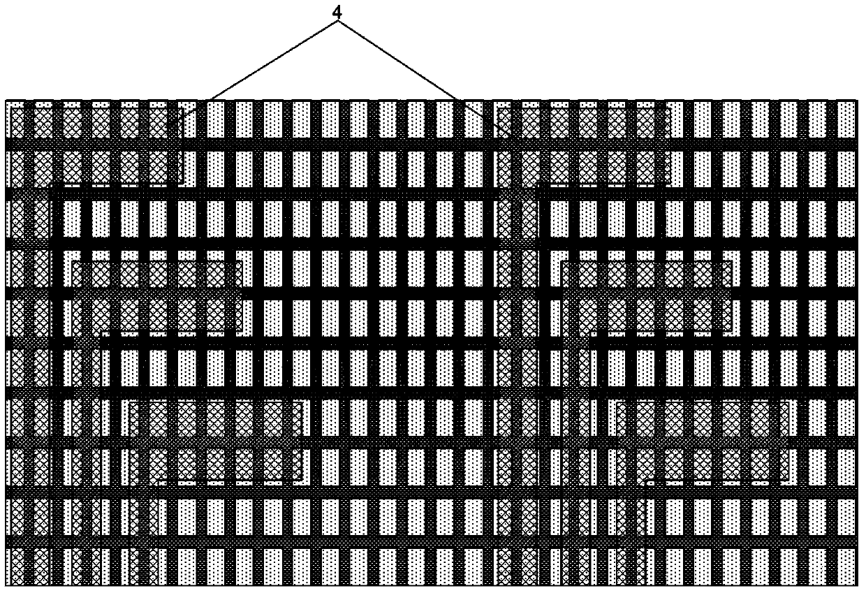
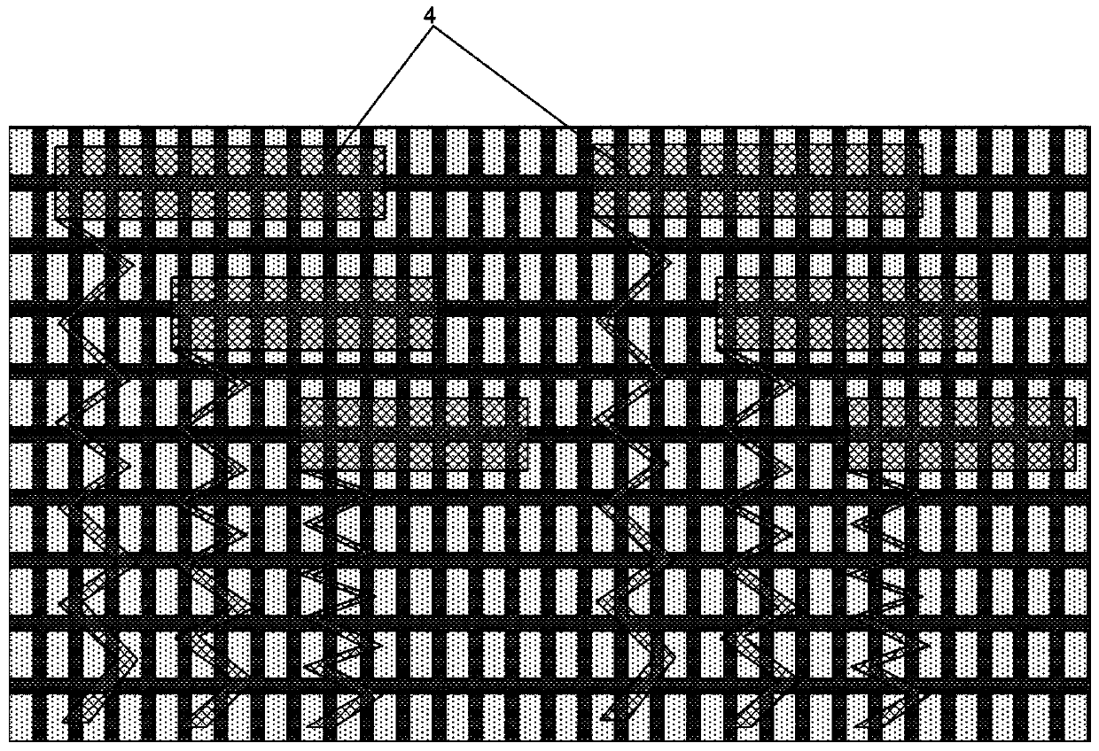
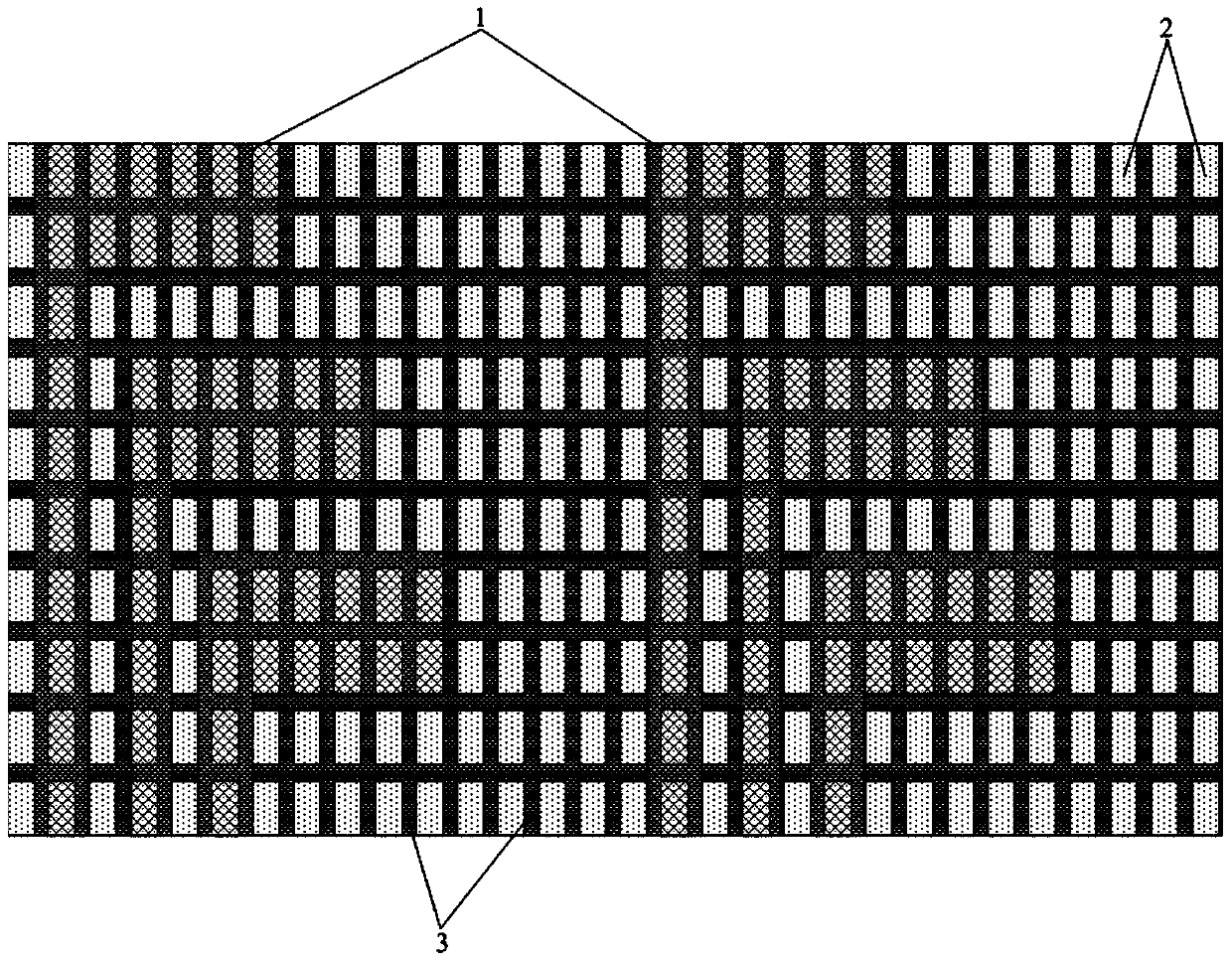
[0025] This embodiment provides a touch screen, such as image 3 As shown, it includes a touch electrode plate 1 and pixel electrodes 2 arranged in a matrix. The touch electrode plate 1 is arranged in the direction of the orthographic projection of the pixel electrodes 2, and a black matrix 3 is also arranged in the direction of the orthographic projection of the pixel electrodes 2. The black matrix 3 corresponds to the area between any adjacent pixel electrodes 2 , the touch electrode plate 1 is located in the orthographic projection direction of the black matrix 3 , and the black matrix 3 completely blocks the edge lines of the touch electrode plate 1 . Wherein, the touch electrode plate 1 is made of indium tin oxide material.

[0026] The above setting description: when the graphic area of ​​the black matrix 3 is negligible, the graphic area of ​​the touch electrode plate is exactly equal to the graphic area of ​​the pixel electrode which is an integer multiple, or the inte...

Embodiment 2

[0032] This embodiment provides a touch screen. The difference from Embodiment 1 is that the first substrate is an array substrate, and the second substrate is a transparent cover. The pixel electrodes are AMOLED pixel electrodes. That is, the touch screen in this embodiment is an on cell AMOLED display touch screen (that is, a touch sensor is disposed on an AMOLED display panel), and the on cell AMOLED display touch screen is easy to manufacture, has a high yield rate, and is widely used.

[0033] Other structures of the touch screen in this embodiment are the same as those in Embodiment 1, and will not be repeated here.

Embodiment 3

[0035] This embodiment provides a touch screen. The difference from Embodiment 1-2 is that the driving electrode plate and the sensing electrode plate are respectively located in two different layers.

[0036] With such an arrangement, it is only necessary to ensure that mutual capacitance is formed between the driving electrode plate and the sensing electrode plate to realize touch control.

[0037] Other structures of the touch screen in this embodiment are the same as those in Embodiment 1 or 2, and will not be repeated here.


PUM


Abstract

The invention provides a touch screen and a display device. The touch screen comprises a touch electrode plate and pixel electrodes arranged in a matrix mode. The touch electrode plate is arranged on the orthographic projection direction of the pixel electrodes. A black matrix is further arranged on the orthographic projection direction of the pixel electrodes. The black matrix corresponds to the area between any two adjacent pixel electrodes. The touch electrode plate is located on the orthographic projection direction of the black matrix, and the black matrix shields the edge line of the touch electrode plate completely. According to the touch screen, the black matrix shields the edge line of the touch electrode plate completely so that touch electrode plates of any graphs can not be seen by the human eyes in the displaying process, and therefore the frame quality in the displaying process of the touch screen can be ensured; the problem of vanishing of the touch electrode plate in the touch screen is solved, and the display effect of the touch screen is improved.

Description

technical field [0001] The present invention relates to the field of display technology, in particular to a touch screen and a display device. Background technique [0002] In recent years, small-sized touch-screen mobile display products have accounted for a considerable proportion in the market. Among them, because on-cell touch-screen display products only need to form simple transparent electrode patterns (patterns of driving electrodes and sensing electrodes) on the surface of the display panel ), the touch display function can be realized, and it is easy to ensure the yield rate, so on cell touch screen display products are the most widely used. [0003] At present, in a single-layer on-cell touch screen, the touch electrode pattern is usually formed by one-time exposure and development process to form the pattern of the driving electrode and the sensing electrode and the pattern of the respective signal lines, and the touch electrode pattern is usually a transparent e...

Claims


Application Information

Patent Timeline
Patent Type & Authority Applications(China)
IPC IPC(8): G06F3/044
CPCG06F3/04164G06F3/0443
Inventor 高永益南英瑛高山
Owner BOE TECH GRP CO LTD
Why Eureka
Try Eureka