
Single-station punching mechanical arm structure

A manipulator and single-station technology, applied in the field of stamping equipment, can solve problems such as easy work-related injuries

Inactive Publication Date: 2014-08-27
吴照文
View PDF7 Cites 6 Cited by
  • Summary
  • Abstract
  • Description
  • Claims
  • Application Information

AI Technical Summary

Problems solved by technology

[0005] In view of the above defects, the present invention provides a single-station stamping manipulator structure which is beneficial to solve the problem of work-related injuries in the traditional stamping industry, which can improve work efficiency and reduce the number of workers. Connected, you can operate synchronously, which can solve many shortcomings of the existing technology

Method used


Image

  • Single-station punching mechanical arm structure
  • Single-station punching mechanical arm structure
  • Single-station punching mechanical arm structure

Examples


Embodiment Construction

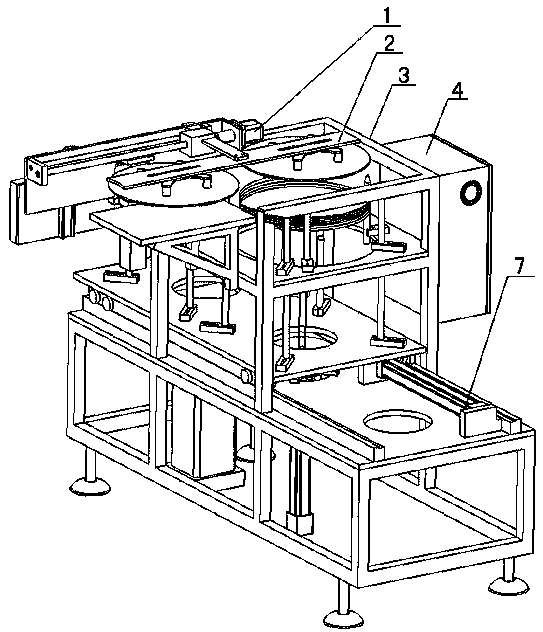
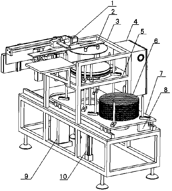
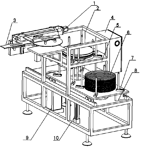
[0023] like Figure 1-8 As shown, the single-station stamping manipulator structure described in the embodiment of the present invention includes a frame power device 1, a feeding frame 2, and a main frame body 3, and the main frame body 3 is composed of an upper frame body and a lower frame body , where the top of the upper frame body is equipped with a feeding frame 2 and connected to the frame power unit 1 at one side of the feeding frame 2, and the middle part of the upper frame body is provided with a material positioning frame 5, and the surface of the lower frame body below the material positioning frame 5 is horizontal Lay a stocking frame 7 and fixedly install a horizontal cylinder 8 in the space between the bottom surface of the stocking frame 7 and the upper surface of the lower frame body, wherein the upper material cylinder 10 is installed in the main frame body 3 below the stocking frame 7, so An oil reservoir 9 is installed inside the lower frame body; meanwhile...


PUM


Abstract

The invention relates to a single-station punching mechanical arm structure which comprises a rack power device, a feeding rack and a main frame, wherein the main frame is composed of an upper frame body and a lower frame body, the feeding rack is installed on the top of the upper frame body, and the rack power device is connected to one side of the feeding rack; a material positioning rack is arranged in the middle of the upper frame body, a material rack is horizontally laid on the surface of the lower frame body below the material positioning rack, and a horizontal cylinder is fixed between the bottom surface of the material rack and the lower frame body; a feeding cylinder is installed in the main frame body below the material rack, an oil storer is installed in the lower frame body, and a power box is fixedly installed outside the main frame. The single-station punching mechanical arm structure has the advantages that when the structure is used, materials are placed on the material rack, pushed to the material positioning rack through the horizontal cylinder, then pushed to a specific height by the feeding cylinder, and finally sent to a needed mold by the feeding rack to be machined, the procedure that materials are placed one by one manually is omitted, the trouble of manual operation is saved, unnecessary material placing mistakes are reduced, a user feels safe, and the number of workers is reduced.

Description

technical field [0001] The present invention relates to stamping equipment technology, in particular to a series of single-station discharge devices suitable for all stamping, such as single-station punch press discharge devices, hydraulic press discharge devices, tapping machine discharge devices, and other stamping peripheral equipment discharge devices Single-station stamping manipulator structure. Background technique [0002] The stamping manipulator is based on the automation equipment and according to the characteristics of stamping production, it is specially developed for the realization of stamping automation and unmanned production. It can replace manual work on material stamping, handling, loading and unloading at each stamping station. For repetitive, dangerous, and high-tempo processing industries such as stamping, this equipment can save labor costs, improve labor and equipment safety, and maintain product productivity, quality, and process stability. A singl...

Claims


Application Information

Patent Timeline
IPC IPC(8): B21D43/10B21D43/18
Inventor 吴照文
Owner 吴照文
Learn More