
Cutting device for drainage pipe of air conditioner
A technology for drainage pipes and air conditioners, which is applied in metal processing and other directions, and can solve problems such as length changes, large differences in the length of corrugated pipes, and easy deformation.
- Summary
- Abstract
- Description
- Claims
- Application Information
AI Technical Summary
Problems solved by technology
Method used
Image

Examples
Embodiment Construction
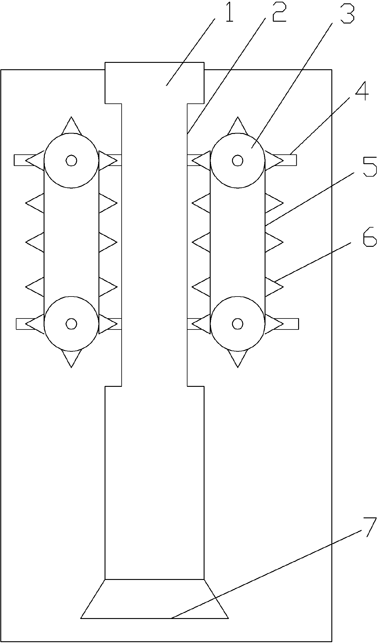
[0007] The reference signs in the accompanying drawings of the description include: feed pipe 1 , feed port 2 , feed wheel 3 , guide chute 4 , feed belt 5 , feed tooth 6 , and feed port 7 .
[0008] Below in conjunction with accompanying drawing and embodiment technical solution of the present invention is described in further detail:
[0009] Such as figure 1 As shown, the present invention provides a feed mechanism for a corrugated drain pipe cutting machine for air conditioning,
[0010] The feed pipe 1 is cylindrical and fixed on the workbench, and the workbench is provided with four guide chutes 4 located on both sides of the feed pipe 1 and arranged symmetrically. The rotating shaft passes through the guide chute 4 and is radially rotatably connected with it, and the rotating shaft can also move along the length direction of the guide chute 4 and be fixed at a certain position of the guide chute 4 . One end of the rotating shaft above the workbench is threadedly connec...
PUM
 Abstract
Description
Claims
Application Information