Eureka AIR delivers breakthrough ideas for toughest innovation challenges, trusted by R&D personnel around the world.

Pattern forming device and pattern forming method

A pattern and axial direction technology, applied in the field of pattern forming device and pattern formation, can solve the problems of large position deviation and inability to perform alignment on one end side, and achieve the effect of position deviation suppression and small relative movement

Inactive Publication Date: 2014-08-27
DAINIPPON SCREEN MTG CO LTD
View PDF8 Cites 0 Cited by
  • Summary
  • Abstract
  • Description
  • Claims
  • Application Information

AI Technical Summary

Problems solved by technology

Therefore, it is easy to cause a positional shift in the process of bringing the two closer together and pressing from this state.
In addition, alignment can be performed on one end side where the substrate and plate are close, but not on the other end side. In addition, in the process of pressing sequentially from one end, the positional deviation may gradually increase.

Method used


Image

  • Pattern forming device and pattern forming method
  • Pattern forming device and pattern forming method
  • Pattern forming device and pattern forming method

Examples


no. 1 approach

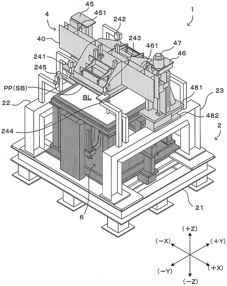
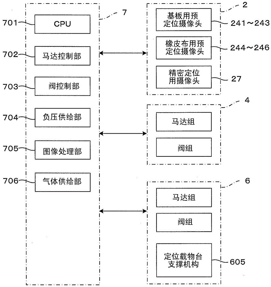
[0064] figure 1 It is a perspective view showing the first embodiment of the pattern forming apparatus of the present invention. In addition, figure 2 It is a block diagram showing the control system of the pattern forming apparatus. In addition, in figure 1 In order to show the internal structure of the device, the state where the external cover is removed is shown. In order to unify the directions in each figure, such as figure 1 Set the XYZ orthogonal coordinate axis as shown on the bottom right. Here, the XY plane represents the horizontal plane, and the Z axis represents the vertical axis. In more detail, the +Z direction indicates the vertical upward direction. When viewed from the device, the front surface direction is the -Y direction, and the movement of accessing the device from the outside, including loading and unloading items, is performed along the Y axis direction.

[0065] The pattern forming apparatus 1 has a structure in which an upper stage part 4 and a dow...

no. 2 approach

[0163] Next, a second embodiment of the pattern forming apparatus of the present invention will be described. The pattern forming apparatus of the second embodiment is different from the pattern forming apparatus 1 of the above-mentioned first embodiment only in a part of the structure of the loading stage. On the other hand, the other structures in the first embodiment, namely the main frame 2, the upper stage portion 4, and the control unit 7, can basically be directly used as the main frame, the upper stage portion, and the control unit in the second embodiment. . Therefore, the following description will focus on the differences from the first embodiment, particularly the structure and operation of the download stage. In addition, the same reference numerals are assigned to the same configurations as those of the first embodiment, and descriptions thereof are omitted.

[0164] Figure 18 It is a figure which shows the main part of the 2nd Embodiment of the pattern forming a...


PUM


Abstract

The invention provides a pattern forming device and a pattern forming method. An architrave shaped download object bench (16) is used for attaching rubber cloth, and a plurality of handle portions (625) capable of respectively rise and fall are used for supporting part of a central part of the rubber cloth. A printing roller unit (64) moves along the lower surface of the rubber cloth to uphold part of the rubber cloth, allowing the rubber cloth to be abutting the plane or substrate arranged above the rubber cloth. As the printing roller unit (64) moves, the handle portions (625) successively declines to retreat downwardly, so as to avoid interface between the handle portions (625) and the printing roller unit (64).

Description

Technical field [0001] The present invention relates to a pattern forming apparatus and a pattern forming method that form a pattern by patterning a pattern forming material carried on a blanket or transferring the formed pattern to a substrate. Background technique [0002] There is a technique of forming a pattern on a substrate such as a glass substrate and a semiconductor substrate, in which a blanket carrying a pattern is closely attached to the substrate to transfer the pattern to the substrate. In addition, there is a technique for supporting a pattern on a blanket. That is, a plate (negative plate) is brought into pressure contact with a uniform film formed on the surface of the blanket by a pattern forming material, so that the Unnecessary parts are attached to the plate and removed, leaving only the patterned parts on the blanket for pattern formation (pattern forming). [0003] As such a technique, for example, the printing technique described in JP 07-125179 A is appli...

Claims


Application Information

Patent Timeline
Patent Type & Authority Applications(China)
IPC IPC(8): B41F16/00B41M5/00
CPCB29C59/02B41F17/14B41F33/00B41P2213/734
Inventor 正司和大川越理史上野博之芝藤弥生增市干雄上野美佳
Owner DAINIPPON SCREEN MTG CO LTD
Why Eureka
Eureka Blog
Learn More