Smart card conveyer belt and smart card conveying mechanism

A conveying mechanism and conveying belt technology, applied in the field of smart card production equipment, can solve problems such as deformation, text cannot be typed, affecting production efficiency, etc., and achieve the effect of accurate position

Inactive Publication Date: 2014-08-27
GUANGZHOU MINGSEN TECH CO LTD
View PDF9 Cites 12 Cited by
  • Summary
  • Abstract
  • Description
  • Claims
  • Application Information

AI Technical Summary

Problems solved by technology

There are two main types of existing smart card conveying mechanisms. The first is to push the card through the card clamping device. card, such as figure 1 and figure 2 As shown, this conveying mechanism includes a conveyor belt and a power mechanism, wherein the conveyor belt includes a synchronous belt body 1, the inner belt surface of the synchronous belt body 1 is provided with timing teeth 2, and the outer belt surface is provided with several The tooth 3 is used to push the card 4. The tooth 3 is formed by extending vertically outward from the outer belt surface of the synchronous belt body 1. When working, the surface of the card is parallel to the belt surface, and the tooth 3 acts on the surface of the card 4. On the edge, push the card 4 to make feeding movement on the coding equipment
The existing conveyor belt has the following disadvantages: since the conveyor belt is a soft component, it is easy to bend and deform. When the reaction force of the card is relatively large during the card process, deformation will still occur; during the process of pushing the card 4 to code, the card 4 will generate a large reaction force F on the card tooth 3 1 (see figure 1 ), the reaction force F 1 A moment T in a plane perpendicular to the belt surface will be generated on the conveyor belt 1 (see figure 1 ), the moment T 1 It will cause the conveyor belt to produce a certain bending deformation in the direction perpendicular to the belt surface, and because the locking tooth 3 itself is integrally formed or connected with the synchronous belt body 1, it will also produce a certain degree of deformation under a large reaction force. Deformation, the combination of these two deformations makes the card 4 deviate from the set posture in the coding equipment, thus affecting the position of the text printed on the card 4, and even part of the text cannot be printed on the card 4

Method used


Image

  • Smart card conveyer belt and smart card conveying mechanism
  • Smart card conveyer belt and smart card conveying mechanism
  • Smart card conveyer belt and smart card conveying mechanism

Examples


Embodiment 1

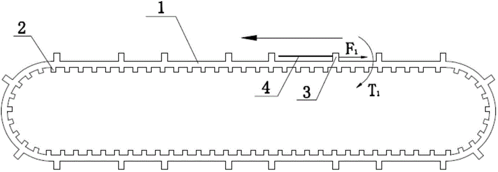
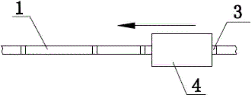
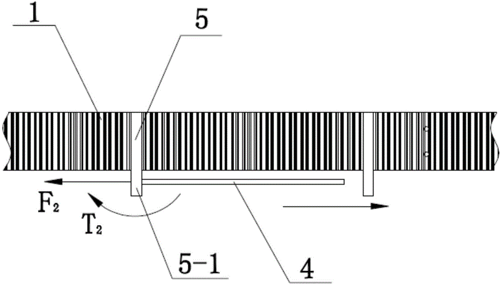
[0038] see Figure 3 to Figure 5 , the smart card conveyor belt of the present invention includes a synchronous belt body 1, which is provided with several rigid shifting teeth 5, and the shifting teeth 5 extend along the height direction of the synchronous belt body 1 and extend out of the synchronous belt The lower edge of the belt body 1 , the protruding part constitutes the card pushing part 5 - 1 for pushing the card 4 .

[0039] see Figure 3 to Figure 5 , the shifting tooth 5 is arranged on the outer belt surface of the synchronous belt body 1, and the shifting tooth 5 and the synchronous belt body 1 are integrally formed. In this way, when the synchronous belt body 1 is formed, the shifting teeth 5 are formed, and the subsequent installation of the shifting teeth 5 can be omitted. The disadvantage is that once the position of the shifting teeth 5 is formed, it cannot be changed.

[0040] see Figure 3 to Figure 5 , the inner belt surface and the outer belt surface o...

Embodiment 2

[0046] The difference between this embodiment and embodiment 1 is:

[0047] see Figure 9 to Figure 12 , In the conveyor belt of this embodiment, the timing belt body 1 is provided with timing teeth 2 only on the inner belt surface. The shifting tooth 5 is an independent member made of metal connected to the synchronous belt body 1. The shifting tooth 5 includes a main rod 5-4 and clamping parts arranged on the back side of the upper and lower ends of the main rod 5-4. A piece 5-2, a clamping space 5-3 for clamping the upper and lower edges of the synchronous belt body 1 is provided between the clamping piece 5-2 and the main rod 5-4, and the clamping Part 5-2, the synchronous belt body 1 and the main rod 5-4 are fixedly connected together by screw connection, wherein the main rod 5-4 is located on the outer surface of the synchronous belt body 1, and the clamping part 5- 2 is located on the inner belt surface of the belt body 1 of the synchronous belt. The joint surface of...

Embodiment 3

[0051] see Figure 14 to Figure 17 The difference between this embodiment and embodiment 2 is that, in this embodiment, the inner belt surface and the outer belt surface of the synchronous belt body 1 are provided with synchronous teeth 2, and the main rod 5- 4 is matched to the tooth groove on the outer belt surface of the synchronous belt body 1, and the clamping part 5-2 is matched to the tooth groove on the inner belt surface of the synchronous belt body 1. Since both sides of the synchronous belt body 1 are provided with synchronous teeth 2, the main rod 5-4 and the clamping part 5-2 can be matched in the tooth groove, which not only facilitates the main rod 5-4 and the clamping part 5 -2 is fixed, and the force-bearing area between the shifting tooth 5 and the synchronous belt body 1 is improved, especially the cooperation between the side of the main rod 5-4 and the clamping part 5-2 and the side of the tooth groove, which can make the affected The force is uniform and...


PUM


Abstract

The invention discloses a smart card conveyer belt and a smart card conveying mechanism. The smart card conveyer belt comprises a conveyer belt body, the conveyer belt body is provided with a plurality of rigid shifting teeth, the shifting teeth extend in the height direction of the conveyer belt body to extend out of the lower edge of the conveyer belt body, and a card pushing part for pushing cards is formed by the extending-out part. The smart card conveying mechanism comprises the conveyer belt and a power mechanism, the power mechanism comprises a motor and at least two synchronization belts, synchronization teeth of the conveyer belt are meshed with tooth grooves in synchronization belt wheels, and one synchronization belt wheel is driven by the motor. By means of the smart card conveyer belt, the shifting teeth cannot be bent and deformed when the cards are pushed to conduct code printing, and it is guaranteed that the positions of printed characters on the cards are accurate.

Description

technical field [0001] The invention relates to production equipment for smart cards, in particular to a smart card conveying belt in a smart card coding process and a smart card conveying mechanism including the conveying belt. Background technique [0002] In the production process of smart cards, it is necessary to code the cards with concave and convex characters (that is, to mark relevant text information on the cards, such as card number, ID number, etc.). In order to make the corresponding text on the designated position of the card. There are two main types of existing smart card conveying mechanisms. The first is to push the card through a card clamping device. This mechanism takes a lot of time in the process of card entry and exit, which affects production efficiency. The second is to push the card through a conveyor belt. card, such as figure 1 and figure 2 As shown, this conveying mechanism includes a conveying belt and a power mechanism, wherein the conveyi...

Claims


Application Information

Patent Timeline
Patent Type & Authority Applications(China)
IPC IPC(8): B65H5/02
Inventor 王开来
Owner GUANGZHOU MINGSEN TECH CO LTD
Why Eureka
Try Eureka