Novel cloth strip cutting mechanism

A cloth cutting and new type of technology, applied in the field of sewing machines, can solve the problems of increasing the production cost of enterprises, obvious installation positions, and poor versatility, and achieve the effects of improving production efficiency, enhancing aesthetics, and strong versatility

Active Publication Date: 2014-08-27
JACK SEWING MASCH CO LTD
View PDF7 Cites 2 Cited by
  • Summary
  • Abstract
  • Description
  • Claims
  • Application Information

AI Technical Summary

Problems solved by technology

[0002] The existing cloth strip cutting mechanism is installed behind the machine head or above the sewing table cover. The above structure has the following defects: it occupies the space near the machine needle above the sewing table cover.
Therefore, the installation position of the existing mechanism is obvious, which affects the appearance, and the versatility is not strong, which virtually increases the production cost of the enterprise

Method used


Image

  • Novel cloth strip cutting mechanism
  • Novel cloth strip cutting mechanism
  • Novel cloth strip cutting mechanism

Examples


Embodiment 1

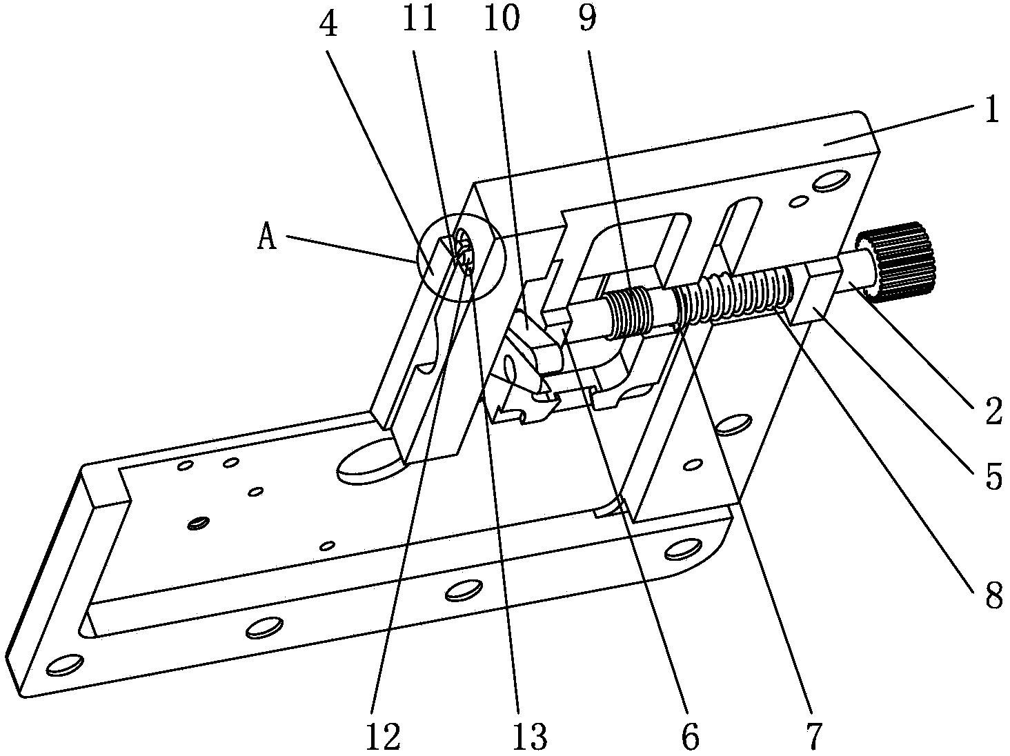
[0029] Example 1: see see figure 1 -5:

[0030] A new type of cloth strip cutting mechanism, including a seaming table cover 1, on the bottom plane of the sewing table cover 1, a rotating seat shaft 2 is arranged, one end of the rotating seat shaft 2 is provided with a moving knife 3, and the other end is passed through a transmission The device is connected with the driver, the movable knife 3 can extend out of the upper plane of the seam cover 1, and the fixed knife 4 is set on the seam cover 1, the movable knife 3 is located on one side of the fixed knife 4, and the driver drives the transmission device to move and then drive The rotating seat shaft 2 and the movable knife 3 rotate, and the fixed knife 4 and the movable knife 3 form a scissors structure. A movable knife groove is provided on the seam cover plate 1, and one end of the movable knife 3 can stretch out of the movable knife groove, and the fixed knife 4 is fixed on the plane of the movable knife groove one side...

Embodiment 2

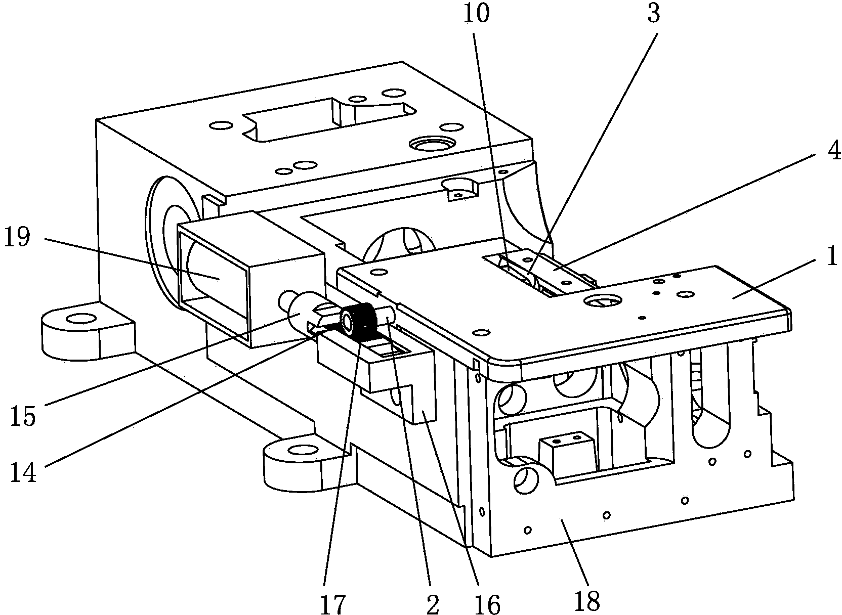
[0042] Example 2: see Figure 6 , 7 :

[0043] The structure of this embodiment is basically the same as that of Embodiment 1. The difference is that the transmission mechanism of this embodiment adopts a gear transmission structure. The specific structure is: a driven gear 20 is arranged on the rotating seat shaft 2, and A driver is arranged on the lower joint 18 of the shell, and the driver is connected with the driving gear 21, and the driving gear 21 and the driven gear 20 are meshed for transmission.

[0044] The driver in this embodiment can be a motor or a rotating electromagnet or the electromagnet 19 .

[0045] The electromagnet 19 is fixed on the lower section 18 of the casing, the head of the iron core of the electromagnet 19 is hinged to one end of the connecting bar 22, and the other end of the connecting bar 22 is hinged on one end face of the driving gear 21, and the driving gear 21 is arranged on the gear On the shaft, the gear shaft is arranged on the lower...

Embodiment 3

[0050] Embodiment 3: see Figure 8 :

[0051] The structure of this embodiment is basically the same as that of Embodiment 1, and the difference is that the transmission mechanism of this embodiment adopts the combination of gear transmission and connecting rod mechanism, and the specific structure is:

[0052] The lower section 18 of the casing is provided with a driver, the output shaft 24 of the driver is provided with a first connecting rod 25, the other end of the first connecting rod 25 is hingedly connected with the second connecting rod 26, and the other end of the second connecting rod 26 is arranged On the end face of the driving gear 27 , the driving gear 27 is arranged on the lower joint 18 of the casing through the gear shaft, and the driven gear 28 meshing with the driving gear 27 is arranged on the rotating seat shaft 2 .

[0053] The driver adopts a motor or a rotating electromagnet 29, and the motor or a rotating electromagnet 29 can be arranged in the lower ...


PUM


Abstract

The invention belongs to the technical field of sewing machines and particularly relates to a novel cloth strip cutting mechanism. The mechanism comprises a sewing table cover plate, a rotation seat shaft is arranged on the bottom plane of the sewing table cover plate, a movable cutter is arranged at one end of the rotation seat shaft, the other end is connected with a driver through a transmission unit, and the movable cutter can stretch out of the upper plane of the sewing table cover plate. A fixed cutter is arranged on the sewing table cover plate, and the movable cutter is arranged on one side of the fixed cutter. The driver drives the transmission unit to act to drive the rotation seat shaft and the movable cutter to rotate, and the fixed cutter and the movable cutter form a scissor structure. According to the mechanism, the movable cutter is disposed below the sewing table cover plate when the movable cutter do not perform cloth cutting actions, and cloth can pass smoothly during roll hem, elastic cord and the like sewing or during cover sewing and splicing sewing of two pieces of large-area cloth, so that the universality is high, equipment or parts are not needed to be changed, the enterprise production cost is reduced, the cloth strip cutting function and the thread braid cutting function are integrated, and the machine is multipurpose.

Description

Technical field: [0001] The invention belongs to the technical field of sewing machines, in particular to a novel cloth strip cutting mechanism. Background technique: [0002] The existing cloth strip cutting mechanism is installed behind the machine head or above the sewing table cover. The above structure has the following defects: it occupies the space near the machine needle above the sewing table cover. For the sewing of hemming, elastic band, etc., the existing mechanism will not affect the sewing process, but when two pieces of fabric with a relatively large area are covered or spliced, the space above the cover plate of the sewing table will be occupied , causing the cloth to fail to pass through smoothly, and the sewing work cannot be carried out. Simultaneously, existing mechanism also can not play the effect of thread-cutting braid. Therefore, when sewing two relatively large pieces of fabric, garment factories need to replace equipment or accessories for sewing...

Claims


Application Information

Patent Timeline
Patent Type & Authority Applications(China)
IPC IPC(8): D05B37/04
Inventor 王名科王志洪建敏陈彬
Owner JACK SEWING MASCH CO LTD
Why Eureka
Try Eureka