
Mini type filtering pressure reducing valve

A filter pressure reducing valve, mini-type technology, applied in the direction of filter separation, safety valve, balance valve, etc., can solve the problems of difficult processing, inconvenient use, increased manufacturing cost, etc., achieve compact and reasonable structure setting, reduce use cost, The effect of reducing manufacturing costs

Active Publication Date: 2014-08-27
NINGBO NEW JIAXING AUTOMATIC IND
View PDF6 Cites 4 Cited by
  • Summary
  • Abstract
  • Description
  • Claims
  • Application Information

AI Technical Summary

Problems solved by technology

[0003] However, due to the unreasonable structural setting of the above-mentioned filter pressure reducing valve, there are the following defects: First, because the valve core and the valve stem are integrally formed, the valve core moves synchronously with the valve stem during operation, and the valve stem is on the diaphragm. Axial movement occurs under friction. In order to ensure the coaxiality of the valve stem movement, the distance between the valve stem and the inner wall of the air hole is generally small. Friction is generated, resulting in a certain resistance between the valve stem and the valve body, which affects the sensitivity of air pressure adjustment; second, because the valve body is usually set in a small volume, it is difficult to process air holes that are suitable for the valve stem in the valve body. Larger, resulting in higher manufacturing costs; third, due to the filter element assembly composed of filter elements, water baffles and fixing screws, the filter element needs to cooperate with the water baffle and fixing screws to be fixedly sleeved in the cyclone blade during installation. It leads to inconvenient installation, low loading and unloading efficiency, and additional manufacturing costs due to multiple parts; fourth, due to the complicated structure and poor versatility of the drain valve, it is inconvenient to use and the cost is high

Method used


Image

  • Mini type filtering pressure reducing valve
  • Mini type filtering pressure reducing valve
  • Mini type filtering pressure reducing valve

Examples


Embodiment Construction

[0017] The present invention will be further described below in conjunction with the accompanying drawings.

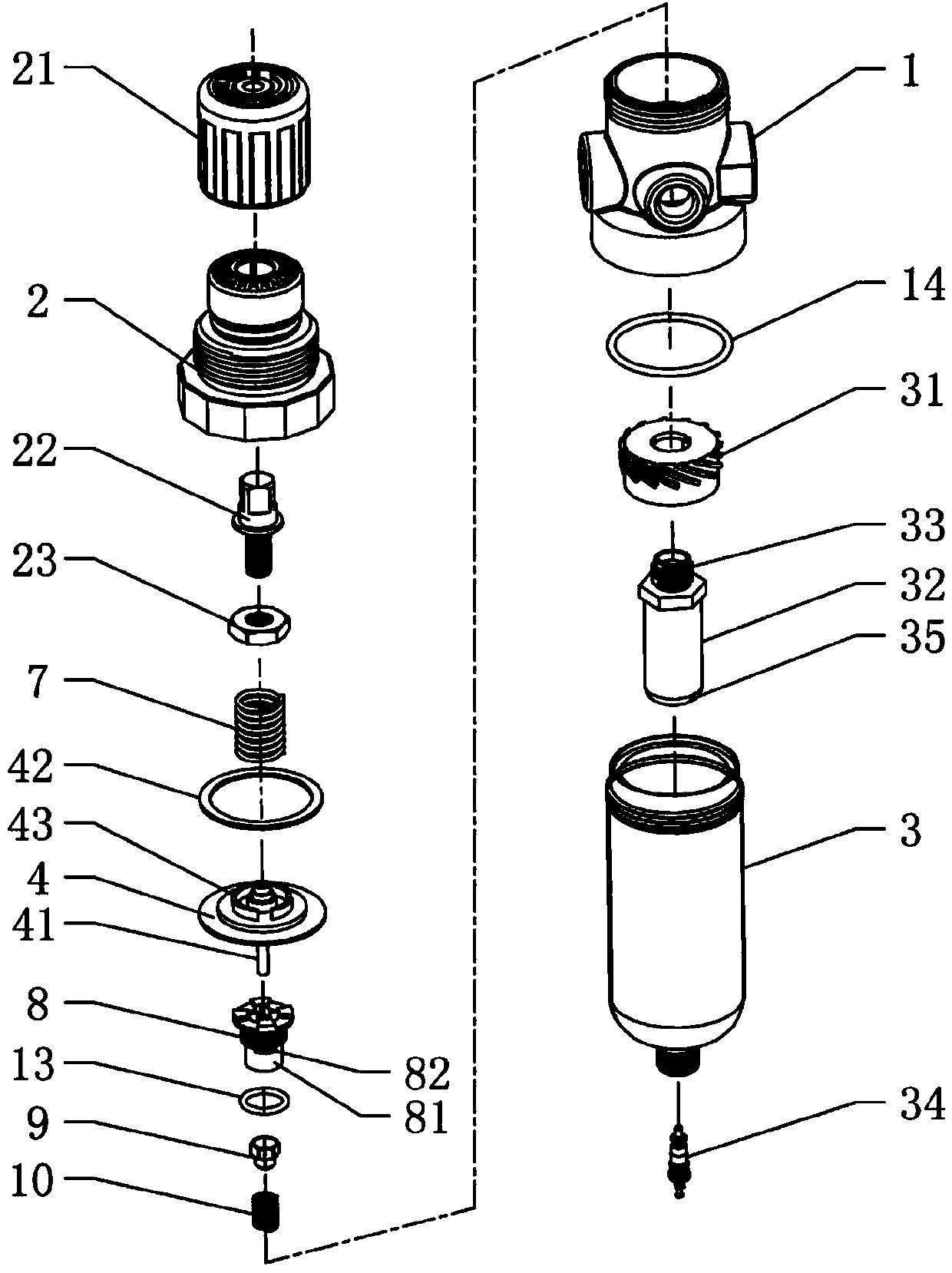
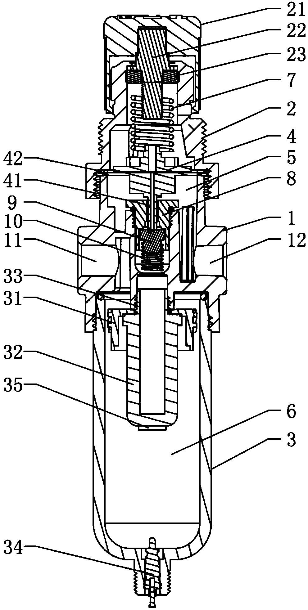
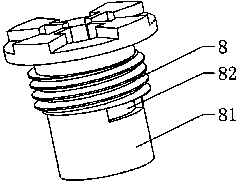
[0018] like Figure 1 to Figure 3 The mini filter pressure reducing valve shown includes a valve body 1, a valve cover 2 that is connected to the upper end of the valve body 1, a water storage cup 3 that is connected to the lower end of the valve body 1, and a valve body 1 and the valve cover 2. The diaphragm 4 between the valve body 1 and the diaphragm 4 cooperate to form an upper chamber 5, and the valve body 1 and the water storage cup 3 cooperate to form a lower chamber 6. The valve body 1 is respectively provided with An air inlet 11 communicating with the lower chamber 6 and an air outlet 12 communicating with the upper chamber 5 .

[0019] The bonnet 2 is provided with an adjusting handwheel 21, and the bonnet 21 is provided with an adjusting screw 22 interlocked with the adjusting handwheel 21, and an adjusting nut 23 corresponding to the adjusting screw 22, t...


PUM


Abstract

A mini type filtering pressure reducing valve comprises a valve body, a valve cover, a water storage cup and a diaphragm. An upper cavity is formed between the valve body and the diaphragm, a lower cavity is formed between the valve body and the water storage cup, an adjusting hand wheel is arranged on the valve cover, an adjusting screw and an adjusting nut are arranged in the valve cover, a filtering mechanism is fixedly arranged in the water storage cup, a fixed seat is installed in the valve body and provided with a through hole for being communicated with the upper cavity and the lower cavity, a valve element is arranged between the fixed seat and the valve body, a push rod is formed at the bottom of the diaphragm, and the bottom end of the push rod penetrates the through hole and is matched with the top end of the valve element in an abutting-against mode. The filtering mechanism comprises a cyclone blade, a one-piece type filter cartridge and a valve core. The one-piece type filter cartridge comprises a filter cartridge body and a threaded connection part integrally formed on the filter cartridge body, and the filter cartridge body is connected to the valve body through the threaded connection part. The mini type filtering pressure reducing valve is simple and reasonable in structure, high in sensitivity, convenient to process, low in manufacturing cost and convenient to install, dismantle and use.

Description

technical field [0001] The invention relates to the technical field of valves, in particular to a mini filter pressure reducing valve. Background technique [0002] The filter pressure reducing valve is to add filter parts on the basis of the pressure reducing valve to ensure the stability of the output air pressure and to filter the air source at the same time, such as removing oil, water, dust and other impurities in the compressed air, which can improve the use of pneumatic components. Longevity and precision in regulating air pressure. The structure of the common filter pressure reducing valve currently on the market usually includes a valve body, a valve cover that is connected to the upper end of the valve body, a water storage cup that is connected to the lower end of the valve body, and a diaphragm between the valve body and the valve cover. , the valve body and the diaphragm cooperate to form an upper chamber, and the valve body and the water storage cup cooperate ...

Claims


Application Information

Patent Timeline
IPC IPC(8): F16K17/20B01D35/04
CPCF16K17/30B01D50/20
Inventor 毛小伟方洋波单杰马武辉
Owner NINGBO NEW JIAXING AUTOMATIC IND
Learn More