Connecting rod fatigue testing device

A fatigue test and connecting rod technology, applied in the direction of machine gear/transmission mechanism testing, etc., can solve problems such as hidden fire hazards, low test efficiency, huge noise, etc., and achieve the effect of improving accuracy and reliability

A fatigue test and connecting rod technology, applied in the direction of machine gear/transmission mechanism testing, etc., can solve problems such as hidden fire hazards, low test efficiency, huge noise, etc., and achieve the effect of improving accuracy and reliability

CN104006967AActive Publication Date: 2014-08-27WEICHAI POWER CO LTD

Image

  • Connecting rod fatigue testing device
  • Connecting rod fatigue testing device
  • Connecting rod fatigue testing device

Examples


Embodiment Construction

[0030] In order to enable those skilled in the art to better understand the technical solutions of the present invention, the present invention will be further described in detail below in conjunction with the accompanying drawings and specific embodiments.

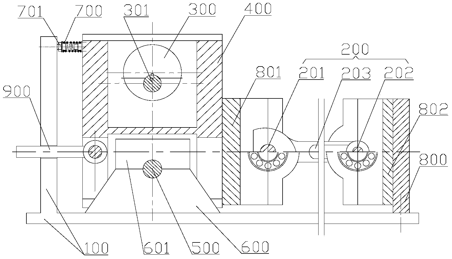
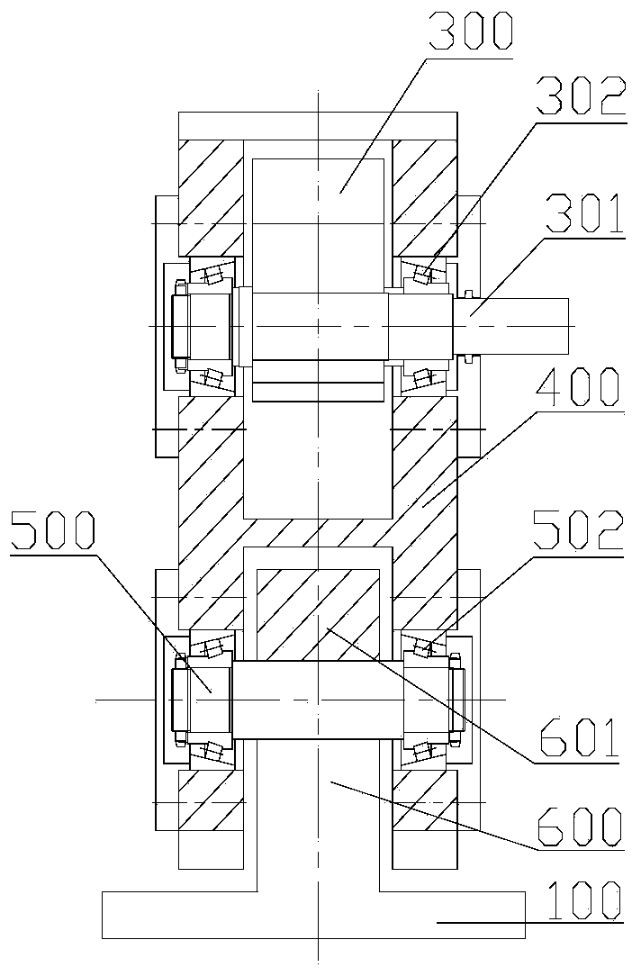
[0031] Please refer to figure 1 and figure 2 , figure 1 A structural schematic diagram of a specific embodiment of the connecting rod fatigue test device provided by the present invention; figure 2 for figure 1 side view.

[0032] The connecting rod fatigue test device includes a base 100, a connecting rod 200 and a loading device for loading the connecting rod 200. One end of the connecting rod 200 is fixed to the base 100, and the other end bears the load from the loading device.

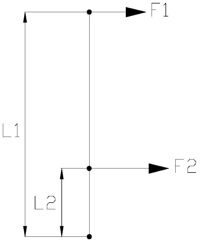
[0033] In fact, when the engine is working, the connecting rod 200 is not only affected by the pressure from the piston, but also by the reciprocating inertia force and the swing inertia force. Although the inertia force is relatively s...


PUM


Abstract

The invention discloses a connecting rod fatigue testing device. The connecting rod fatigue testing device comprises a base, a connecting rod and a loading device. One end of the connecting rod is fixed to the base, the other end of the connecting rod is loaded by the loading device, and the loading device repeatedly exerts continuously-changing pressure and tension on the connecting rod. The tension load and the pressure load change continuously from zero to the amplitude value, and the tension and the pressure are converted automatically instead of being exerted or removed forcefully, namely, the stress process of the connecting rod is continuous. Due to the fact that the connecting rod does not bear suddenly-changing loads, the problem of excessive shock is avoided, the phenomenon that a testing result is abnormal cannot occur and the accuracy and the reliability of the testing result are improved.

Description

technical field [0001] The invention relates to the technical field of engines, in particular to a connecting rod fatigue test device. Background technique [0002] The connecting rod is an important component in the engine. It has a connecting rod small end, a connecting rod large end and a connecting rod body connected between the two, wherein the connecting rod small end is used to install the piston pin and is connected to the piston; the connecting rod large end It is used to connect the crankpin, which in turn connects with the crankshaft. [0003] During the working process of the engine, the connecting rod is always under the pressure of the gas in the cylinder and the reciprocating inertial force, and transmits the interaction force between the piston and the crankshaft, for example, converting the reciprocating linear motion of the piston into the rotational motion of the crankshaft. At any moment in the four strokes of the engine, the force on the connecting rod ...

Claims


Application Information

Patent Timeline
27 Aug 2014
Publication
CN104006967A
IPC
G01M13/02
Inventors
季炳伟; 杨建法