Clutch/brake unit for an accumulation conveyor

A braking unit, storage and transportation machine technology, applied in conveyors, conveyor objects, transportation and packaging, etc., can solve the problems of complex and expensive single-piece manufacturing, and achieve the effect of reducing the number and reliable joint.

Active Publication Date: 2014-08-27
KNAPP AG
View PDF10 Cites 3 Cited by
  • Summary
  • Abstract
  • Description
  • Claims
  • Application Information

AI Technical Summary

Problems solved by technology

[0003] The known engagement-braking unit has the disadvantage that it is expensive and complicated to manufacture due to its large number of individual parts

Method used


Image

  • Clutch/brake unit for an accumulation conveyor
  • Clutch/brake unit for an accumulation conveyor
  • Clutch/brake unit for an accumulation conveyor

Examples


Embodiment Construction

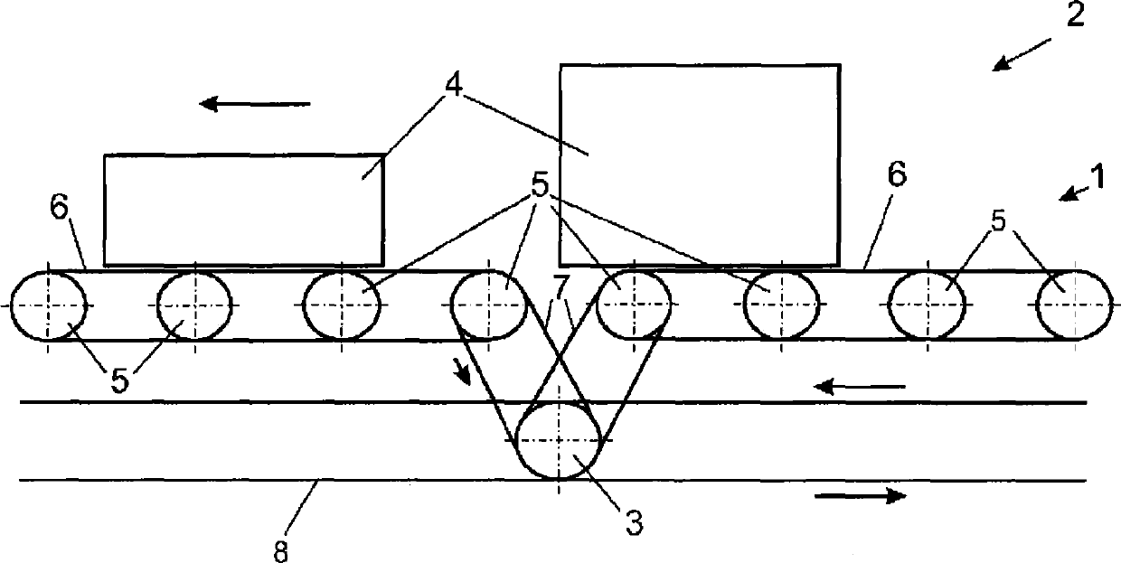
[0015] figure 1 A section of the roller table 1 of the conveyor 2 with the engaging and braking unit 3 is shown schematically. Use the storage and transportation machine 2 to transport the goods 4 (for example, from the warehouse to the entrusted place), so that the goods 4 are gathered from two conveyor belts to one. In order to prevent the items 4 from colliding, the items are accelerated and braked accordingly in certain sections of the roller conveyor 1 . roller table 1 in figure 1 The section shown in has eight rollers 5 which are connected to one another by means of continuous traction means 6 . The higher-level control unit prescribes control information: when the rollers 5 of the roller table 1 are to be braked or accelerated.

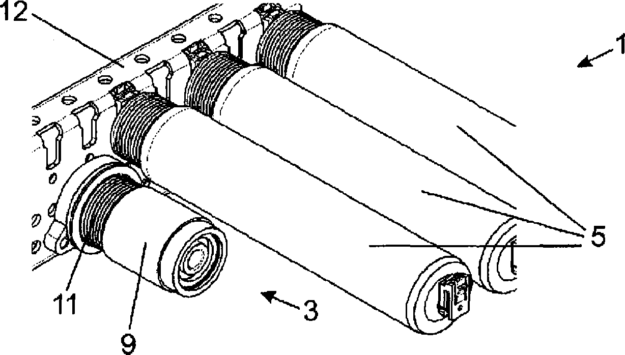
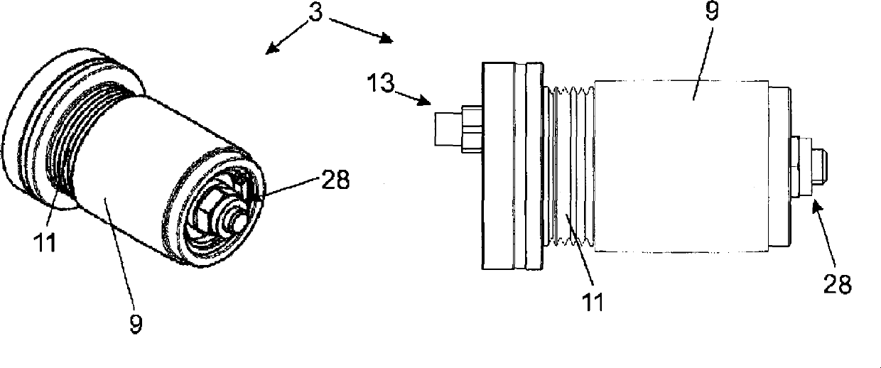
[0016] In order to drive the rollers 5 accordingly, the conveyor 2 has a coupling-brake unit 3 which is connected to the rollers 5 via two continuous traction means 7 formed by V-belts. The coupling-braking unit 3 is continuously driven by ...


PUM


Abstract

A clutch / brake unit for an accumulating conveyor. The clutch / brake unit is driven continuously during operation via an endless drive traction mechanism on a driving roller and is configured, in an engaged operating state, for transmitting the rotational movement of the driving roller about an axis to a driven roller and, in a braking operating state, for slowing down the driven roller on a housing of the clutch / brake unit. The driven roller is connected to the roller via the endless traction mechanism. A first actuating mechanism is configured for displacing the driven roller along the axis in the direction of the housing in order to shift the clutch / brake unit into its braking operating state, and a second actuating mechanism is configured for displacing the driven roller along the axis in the direction of the driving roller in order to shift the clutch / brake unit into its engaged operating state.

Description

technical field [0001] The invention relates to storage and transportation machines An engaging-braking unit for driving and braking at least one roller arranged for transporting items on a roller table of a storage and handling machine by means of continuous traction means, wherein the engaging-braking unit passes through during operation The continuous drive-traction device at the driving roller is continuously driven and is designed to transmit the rotational movement of the driving roller about the shaft to the driven roller in the engaged operating state and to The engagement-braking unit brakes the driven roller at the housing, wherein the driven roller is connected to the roller by means of continuous traction means. Background technique [0002] Document EP 1 314 663 A1 discloses a coupling-brake unit in which both the first and the second actuating means are formed by electrically actuatable coupling magnets. The transmission disc and the output roller are connec...

Claims


Application Information

Patent Timeline
Patent Type & Authority Applications(China)
IPC IPC(8): B65G13/071B65G47/26
CPCB65G13/073B65G47/261B65G13/06B65G13/075B65G23/26
Inventor F·马蒂J·伯格曼恩W·沃克曼恩
Owner KNAPP AG
Why Eureka
Try Eureka