
Visual disparity adjusting apparatus, image processing apparatus, and frame format

A technology of an image processing device and an adjustment device, which is applied in the directions of image communication, TV, color TV, etc., can solve problems such as heavy burden on users, and achieve the effect of solving adverse effects.

Inactive Publication Date: 2014-08-27
SONY CORP
View PDF1 Cites 6 Cited by
  • Summary
  • Abstract
  • Description
  • Claims
  • Application Information

AI Technical Summary

Problems solved by technology

Specifically, when the parallax variation is large, for example, when a part of the image protrudes excessively or an object protrudes unnecessarily during display of a moving image, the burden on the user becomes heavy

Method used


Image

  • Visual disparity adjusting apparatus, image processing apparatus, and frame format
  • Visual disparity adjusting apparatus, image processing apparatus, and frame format
  • Visual disparity adjusting apparatus, image processing apparatus, and frame format

Examples


Embodiment Construction

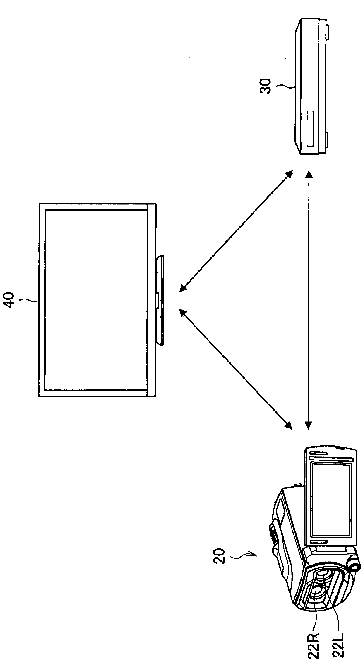
[0035] Hereinafter, preferred embodiments of the present invention will be described in detail with reference to the accompanying drawings. Note: In this specification and the drawings, elements that have substantially the same function and structure are denoted by the same reference numerals, and repeated explanations are omitted.

[0036] In addition, in the specification and drawings, sometimes different characters are appended to the same reference numerals to distinguish from each other a plurality of constituent elements having substantially the same functional structure. However, when there is no need to distinguish a plurality of constituent elements having substantially the same functional structure, only the same reference numerals are given.

[0037] The present invention will be described in the following order of items.

[0038] 1. Structure of image processing system

[0039] 2. Structure and Operation of the Imaging Device

[0040] 3. Structure of playback de...


PUM


Abstract

A visual disparity adjusting apparatus comprises: a visual disparity adjusting unit that performs a visual disparity adjustment between left-eye and right-eye images obtained by image pickup; and a data processing unit that associates metadata, which is related to the visual disparity adjustment, with image data including the left-eye and right-eye images.

Description

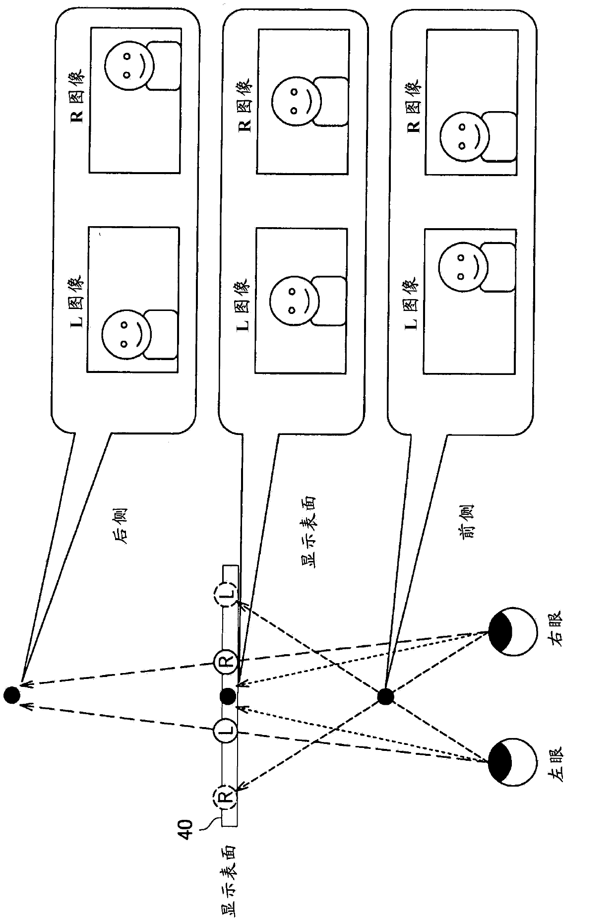
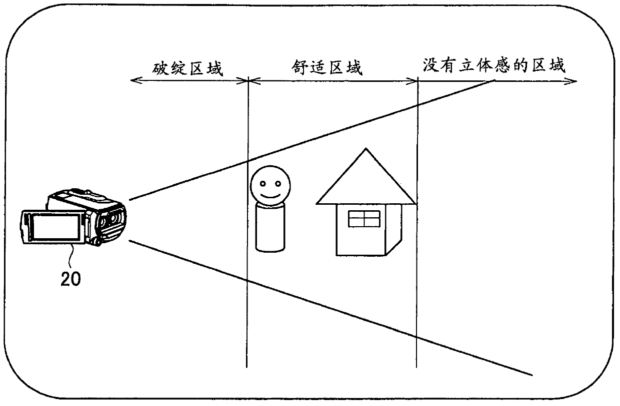
technical field [0001] The present invention relates to a parallax adjustment device, an image processing device and a frame format. Background technique [0002] In recent years, 3D display devices capable of causing a user to perceive a stereoscopic image by displaying a left-eye image (L image) and a right-eye image (R image) have been distributed. In stereoscopic images displayed by these 3D display devices, for example, a difference in baseline length or a convergence angle between when displayed and when imaged and recorded, or a difference in focal length even when the convergence angle is the same as in the real world, may is the cause of visual fatigue. Specifically, when the parallax varies greatly, for example, when a part of an image is excessively protruded or an object is unnecessarily protruded during display of a moving image, the burden on the user becomes heavy. [0003] From this point of view, techniques for performing comfortable 3D display have been d...

Claims


Application Information

Patent Timeline
Patent Type & Authority Applications(China)
IPC IPC(8): H04N13/02G03B35/08G03B35/18H04N5/225H04N5/91H04N5/92H04N13/04
CPCH04N5/77H04N13/0033H04N13/0022H04N13/0066H04N2213/002H04N5/772H04N9/8205H04N9/8227H04N13/144H04N13/128H04N13/178H04N13/31
Inventor 五味圭三大谷孝英后藤健志
Owner SONY CORP
Learn More