Plastic injection mold with rotating ejection demolding function for oblique thread workpieces

A technology of rotary ejection and injection mold, which is applied in the field of injection mold, can solve the problems such as the inability to realize the demoulding of plastic parts and the difficulty of demoulding, and achieve the effect of improving the use efficiency and service life, high demoulding efficiency and simple design

Inactive Publication Date: 2014-09-03
KUNSHAN DAJIU ELECTRONICS
View PDF3 Cites 3 Cited by
  • Summary
  • Abstract
  • Description
  • Claims
  • Application Information

AI Technical Summary

Problems solved by technology

[0002] Injection molds are widely used in the processing and molding of plastic products. However, when processing workpieces with oblique thread structures, such as screws, nuts, helical gears, etc., due to the It is a helical line, and the tooth shape has a certain angle of helix angle. After the plastic part is injection molded, the conventional ejection method cannot realize the demoulding of the plastic part. The helical gear itself rotates in the direction in which the tooth shape is inclined, so as to achieve the purpose of smooth demoulding
Especially for plastic double helical gears, in addition to solving the problem of tooth-shaped cavity rotation or gear plastic part rotation, it is also necessary to solve the difficulty of demoulding caused by the different "pitches" of the two helical gears.
[0003] The existing demoulding method of this type of injection mold is mainly forced demoulding, but this method is only suitable for plastic parts with good toughness and small gear helix angle. and when the thickness of the tooth profile is thin

Method used


Image

  • Plastic injection mold with rotating ejection demolding function for oblique thread workpieces
  • Plastic injection mold with rotating ejection demolding function for oblique thread workpieces

Examples


Embodiment Construction

[0017] The present invention will be specifically introduced below in conjunction with the accompanying drawings and specific embodiments.

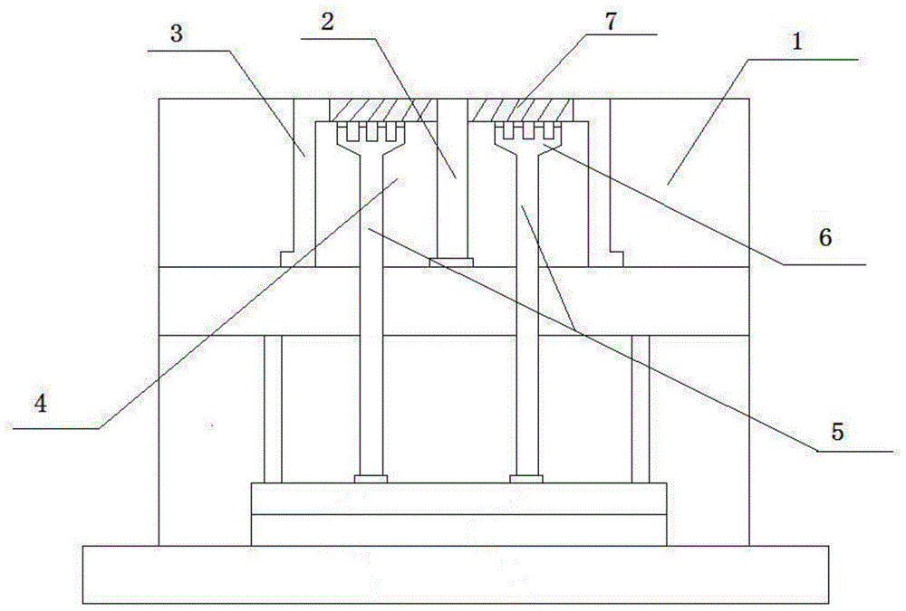
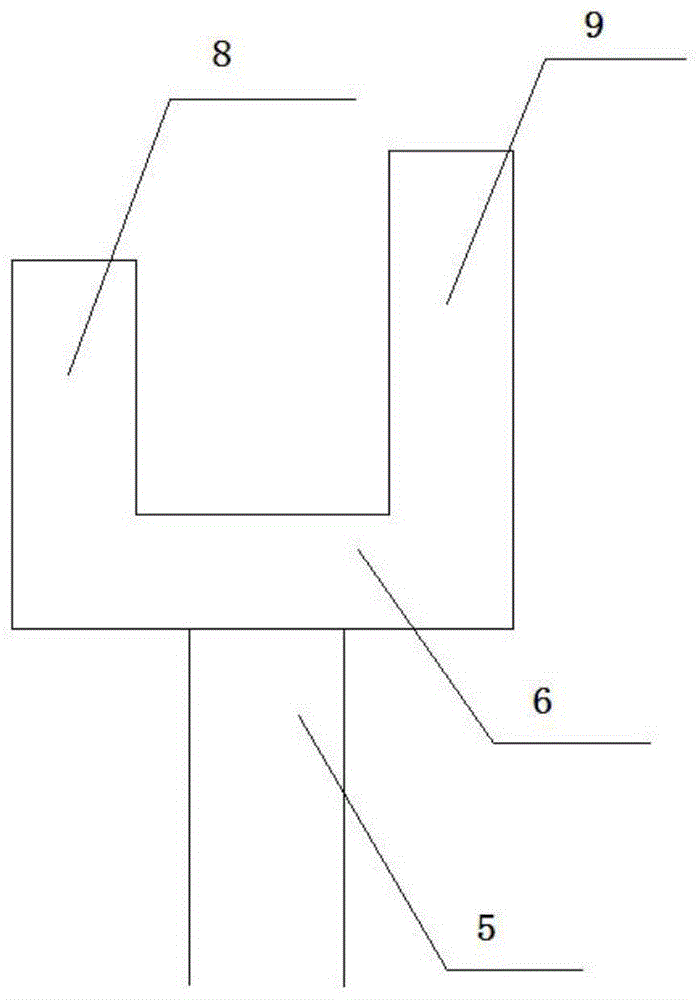
[0018] combine figure 1 , the injection mold with oblique threaded workpieces of the present invention is rotated and ejected from the mold, including a movable template 1 and a base, and the middle part of the movable template 1 away from the end of the base is provided with a cavity insert 4, and the cavity insert 4 is connected with The tooth-shaped cavity 3 is used for injection molding of the workpiece 7. The middle part of the tooth-shaped cavity 3 is provided with a core 2, and the core 2 passes through the cavity insert 4 at the same time; the base end of the movable template 1 is provided with a There is a push rod seat, the push rod seat is provided with 2 push rods 5, and the 2 push rods 5 are distributed on both sides of the core 2, the free end of the push rod 5 is provided with a push claw 6, and the push rod 5 is provided w...


PUM

PropertyMeasurementUnit
lengthaaaaaaaaaa
lengthaaaaaaaaaa
lengthaaaaaaaaaa

Abstract

The invention discloses a plastic injection mold with a rotating ejection demolding function for oblique thread workpieces. The plastic injection mold comprises a movable mold plate and a base, wherein a cavity insert is arranged at the middle part (away from the base end) of the movable mold plate; the cavity insert is connected with a toothed cavity; a mold core is arranged in the middle of the toothed cavity and penetrates through the cavity insert; a push rod seat is arranged at the base end of the movable mold plate; two push rods are arranged on the push rod seat and are distributed at two sides of the mold core; the free end of each push rod is provided with a push claw which is provided with two rows of claws; the two rows of claws are different in height and are a row of high claws and a row of low claws, respectively; the free ends of the high claws are connected with the outer side of the toothed cavity; and the free ends of the low claws are connected with the side edge of a spiral groove of the toothed cavity. The plastic injection mold has the advantage that on the basis of the characteristic of an oblique thread structure, when the high and low claws eject workpieces out, the toothed cavity is driven to rotate, so that the workpieces can be successfully demolded; the rotation is flexible, the push operation is labor-saving and the demolding efficiency is high.

Description

technical field [0001] The invention relates to the field of injection molds, in particular to an injection mold with oblique thread workpieces that are rotated and ejected for demoulding. Background technique [0002] Injection molds are widely used in the processing and molding of plastic products. However, when processing workpieces with oblique thread structures, such as screws, nuts, helical gears, etc., because their tooth lines are helical lines, the tooth shape has a certain angle of helix angle, plastic After the parts are injection molded, the conventional ejection method cannot realize the demoulding of the plastic parts. It is required that the ejection mechanism is pushed out in the direction of demoulding, and at the same time, the molded tooth-shaped cavity or the plastic helical gear itself rotates in the direction of the tooth-shaped inclination. To achieve the purpose of smooth demoulding. Especially for plastic double helical gears, in addition to solvin...

Claims


Application Information

Patent Timeline
Patent Type & Authority Applications(China)
IPC IPC(8): B29C45/40B29C45/26
CPCB29C45/40B29C45/26
Inventor 王枫
Owner KUNSHAN DAJIU ELECTRONICS
Why Eureka
Try Eureka