Construction machine

A technology for construction machinery and loaders, which is applied to cranes, mechanically driven excavators/dredgers, earth movers/shovels, etc., can solve problems such as accelerated hose damage and hydraulic system failures, to avoid impact, The effect of reducing the number of failures and saving time

Inactive Publication Date: 2014-09-03
LEIBHERR HYDRAULIKBAGGER GMBH
View PDF5 Cites 2 Cited by
  • Summary
  • Abstract
  • Description
  • Claims
  • Application Information

AI Technical Summary

Problems solved by technology

[0007] These strains and relative motions of the hydraulic lines at the instantaneous center can create or accelerate hose damage which can lead to failure of the hydraulic system
In this respect, it is particularly problematic that undefined bending and torsional strains appear as an uncontrolled superposition of different strains, which can have a very negative effect on the service life of hydraulic lines

Method used


Image

  • Construction machine
  • Construction machine
  • Construction machine

Examples


Embodiment Construction

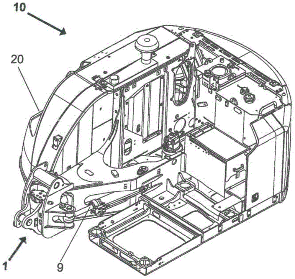
[0032] figure 1The structure shown in represents the superstructure 10 of the construction machine according to the invention. For example, the construction machine may be a mobile excavator or a conveyor designed like a mobile excavator, comprising a chassis (not shown) supporting the travel gears and a superstructure 10 pivotally connected to the chassis.

[0033] For this purpose, for construction machines of this class, the chassis carries a traction gear, which can be designed, for example, as a simple wheeled traction gear or as a tracked traction gear. Here, the type of travel gear used is not relevant for the invention.

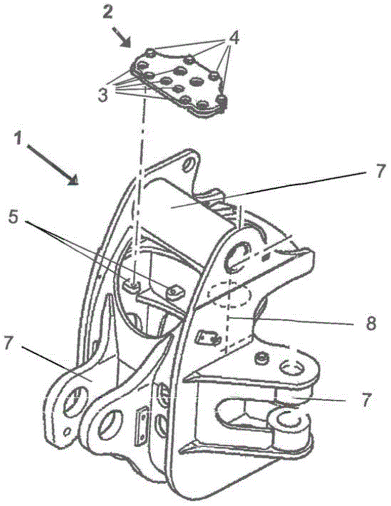
[0034] The superstructure 10 mainly comprises a rotating platform, on the upper side and the side walls of which are arranged on the right side in the direction of travel, all modules of the superstructure 10 are arranged on standard interfaces. In the front region of the superstructure 10 there is a pivot bearing 1 , in this case for receiving a pi...


PUM


Abstract

The machine has a hydraulic attachment i.e. arm, including a pivot bearing (1). A separator plate (2) is provided at the pivot bearing. The separator plate is connectable to the pivot bearing and to hydraulic lines. The separator plate includes a first connection section (3) to which the hydraulic lines are connectable to one another and / or to the separator plate. The hydraulic lines are arranged in an interior region of the attachment. The separator plate is made from a metal material, a metal alloy material, a fiber composite material, a plastic material or another material having torsional stiffness.

Description

technical field [0001] The invention relates to a construction machine with an attachment having at least one pivot bearing and a hydraulic line extending through the pivot bearing. Background technique [0002] Construction machines such as excavators, loaders or cranes have attachments which, depending on their field of application, are configured as excavator arms, loader arms or crane arms or the like. In this respect, they have different parts arranged to be movable relative to each other. [0003] The excavator arm includes an additional component, such as a bucket, and one or more components that are rotatably supported relative to each other by joints or pivot bearings. In this respect, the movements of the various components of the attachment are typically produced by hydraulic cylinders respectively connected to the components of the attachment. However, it is also conceivable to use drives other than hydraulic transmissions to move the attachment or parts thereo...

Claims


Application Information

Patent Timeline
Patent Type & Authority Applications(China)
IPC IPC(8): E02F3/38E02F3/42E02F9/22
CPCE02F3/3695B66C23/64E02F3/382E02F9/2275E02F3/384
Inventor 丹尼尔·维罗索斯蒂芬·肖特迈克尔·罗伊特林格尔德里克·阿萨姆
Owner LEIBHERR HYDRAULIKBAGGER GMBH
Why Eureka
Try Eureka