High-pressure fuel supply pump and diesel engine having such high-pressure fuel supply pump

An oil supply pump and high pressure technology, applied in the direction of mechanical equipment, fuel injection pumps, engine components, etc., can solve the problem that the size of the oil inlet spool cannot be further increased, and can reduce the error chain, improve oil absorption efficiency, and improve efficiency effect

Active Publication Date: 2019-04-23
ROBERT BOSCH GMBH
View PDF5 Cites 0 Cited by
  • Summary
  • Abstract
  • Description
  • Claims
  • Application Information

AI Technical Summary

Problems solved by technology

[0005] In addition, for the plunger type high-pressure oil supply pump in the prior art, the oil outlet valve seat must be set between the oil inlet valve seat and the oil outlet joint.
Because the oil outlet valve seat must be smaller due to space constraints, the oil suction cavity formed in the oil outlet valve seat for accommodating the oil inlet valve core cannot be further enlarged, which also makes it impossible to further increase the oil inlet valve core size of

Method used


Image

  • High-pressure fuel supply pump and diesel engine having such high-pressure fuel supply pump
  • High-pressure fuel supply pump and diesel engine having such high-pressure fuel supply pump
  • High-pressure fuel supply pump and diesel engine having such high-pressure fuel supply pump

Examples


Embodiment Construction

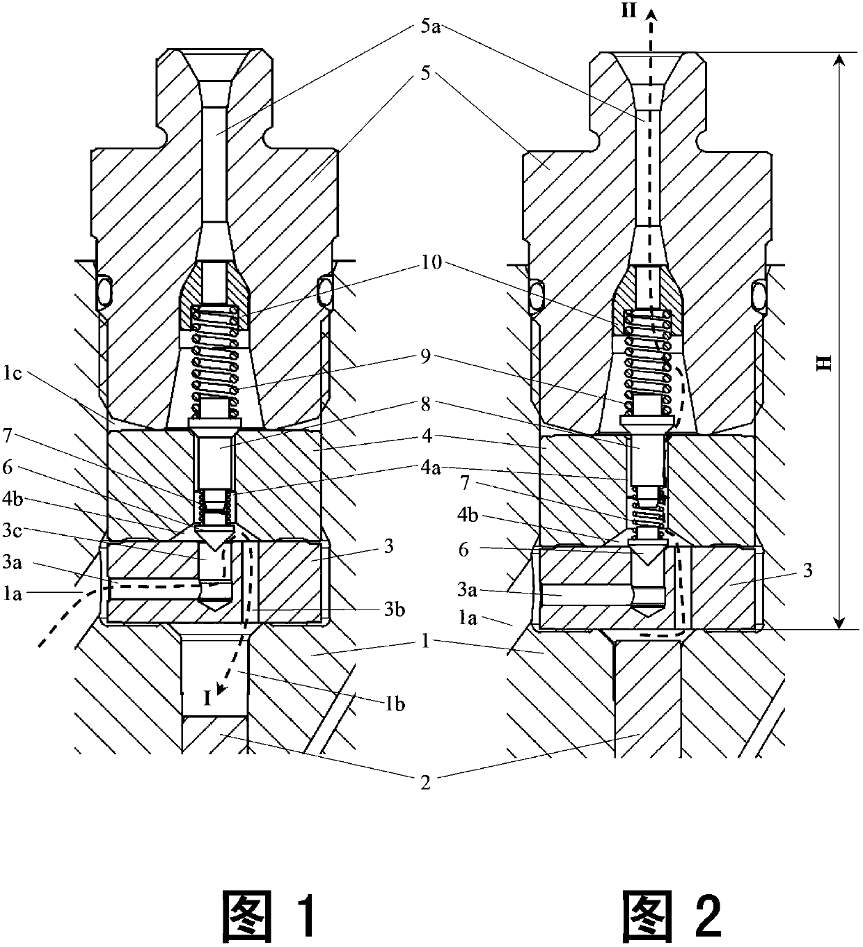
[0036] Illustrative embodiments of the present invention are described below with reference to the accompanying drawings. It should be noted that the same reference numerals in the drawings represent elements or components with the same function and / or structure. In addition, it should be pointed out that the cross-sectional views in the accompanying drawings refer to the cross-sectional views cut along the central axis of the high-pressure fuel supply pump.

[0037] In order to understand the technical solution more clearly, taking the plunger oil pump as an example, first refer to figure 1 and 2 Briefly introduce the high-pressure oil supply pump and its working principle in the prior art, among which figure 1 shows a prior art high pressure fuel supply pump in an oil suction state, and figure 2 A prior art high pressure fuel supply pump is shown in a state of oil pressure.

[0038] like figure 1 and 2 As shown, this high-pressure oil supply pump mainly includes a plu...


PUM


Abstract

The present invention relates to a high-pressure fuel supplying pump, comprising: a barrel (1) formed with a fuel feeding port (1a), a plunger hole (1b) and a receiving chamber (1c) which communicate with each other; and a plunger (2) which is able to reciprocate in the plunger hole, wherein installed in the receiving chamber are an inlet valve body (11) and a valve holder (13) which abut hermetically against each other, an input fuel passage (11a-11c) is formed in the inlet valve body (11) so as to communicate the fuel feeding port (1a) with the plunger hole (1b), a pressure chamber (13b) communicating with the plunger hole (1b) is formed at an end of the valve holder (13) contacting with the inlet valve body (11), an inlet valve core (12) is disposed in the pressure chamber (13b), the inlet valve core (12) is matable with the inlet valve body (11) so as to define a first sealing interface therebetween, and the first sealing interface is openable or closable such that it allows the input fuel passage (11a-11c) selectively to communicate with the pressure chamber (13b) or to isolate from the pressure chamber (13b), and wherein an output fuel passage (13a) is formed in the valve holder (13) to communicate with the pressure chamber (13b), and the valve holder (13) is provided in such a way that it allows the output fuel passage (13a) selectively to communicate with the pressure chamber (13b) or to isolate from the pressure chamber (13b). The present invention also relates to a diesel engine having said high-pressure fuel supplying pump.

Description

technical field [0001] The present invention relates to a high-pressure fuel supply pump for a diesel engine and a diesel engine with the high-pressure fuel supply pump. Background technique [0002] In current diesel engines, fuel is injected into the common rail after being pressurized by a high-pressure fuel supply pump, and then injected into the engine from the common rail in a controlled manner. Usually, the high-pressure oil supply pump is a plunger type oil pump, which mainly includes a plunger sleeve and a plunger, wherein an oil inlet valve seat, an oil inlet valve core, an oil outlet valve seat, and an oil outlet valve are sequentially installed in the plunger sleeve. Core and oil outlet connector. The plunger is driven by the camshaft driven by the engine, and reciprocates in the plunger sleeve, so that the inhaled fuel can be pressurized and the pressurized fuel can be injected into the common rail through the oil outlet joint. [0003] In this high-pressure o...

Claims


Application Information

Patent Timeline
Patent Type & Authority Patents(China)
IPC IPC(8): F02M59/02
CPCF02M59/462F02M59/102F02M59/464
Inventor 张建新金鑫唐朝晖
Owner ROBERT BOSCH GMBH
Why Eureka
Try Eureka