Traction molecular pump embedded inside the device

A technology of embedded devices and molecular pumps, applied in the field of molecular pumps, to achieve the effect of reducing screws and other parts, reducing processing difficulty, and ensuring the flow area

Active Publication Date: 2016-06-22
RES INST OF PHYSICAL & CHEM ENG OF NUCLEAR IND
View PDF4 Cites 0 Cited by
  • Summary
  • Abstract
  • Description
  • Claims
  • Application Information

AI Technical Summary

Problems solved by technology

However, if this rotating part is to work at a high speed, it cannot meet the requirements only by external evacuation devices, so it is necessary to design a molecular pump system that can be directly embedded in the device to evacuate it. deal with

Method used


Image

  • Traction molecular pump embedded inside the device
  • Traction molecular pump embedded inside the device
  • Traction molecular pump embedded inside the device

Examples


Embodiment Construction

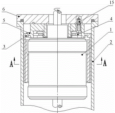
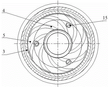
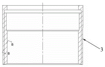
[0030] The traction molecular pump embedded in the device of the present invention will be described in detail below in conjunction with the embodiments and accompanying drawings:

[0031] Such as Figure 1~8 As shown, a traction molecular pump embedded in the device includes a housing 2 with a cylindrical rotor 1 installed inside, and a hollow cylindrical first-stage molecular pump 3 coaxial with the rotor 1. The first-stage molecular pump The pump 3 is located between the side elevation of the rotor 1 and the inner wall of the casing 2, and the inner wall of the first-stage molecular pump 3 forms a spiral air pumping groove 7; The annular flange 8 forms a plurality of air extraction grooves 9 on the lower end surface. In this embodiment, the number of air extraction grooves 9 is 8, and a central through hole 10 is formed in the middle. The inner wall of the central through hole 10 forms a spiral air extraction groove 7. The lower part of the three-stage molecular pump 5 for...


PUM


Abstract

The invention discloses a traction type molecular pump embedded in a device, which comprises a shell with a rotor installed inside, a first-stage molecular pump whose inner wall forms a helical suction groove and is coaxial with the rotor; and is interference-connected with the first-stage molecular pump The upper end surface of the third-stage molecular pump forms an upper annular flange, the lower end surface forms a plurality of air extraction grooves, a central through hole is formed in the middle, the inner wall of the central through hole forms a spiral air extraction groove, and the lower part of the third-stage molecular pump forms a ring Shaped assembly grooves; the lower end surface of the ring-shaped second-stage molecular pump that is interference-fitted with the assembly groove in the third-stage molecular pump forms a plurality of suction grooves, and the edge of the second-stage molecular pump forms a plurality of holes corresponding to the screw holes. groove. The invention has the characteristics of low processing cost and easy processing and installation; and the invention utilizes the characteristics of the high-speed rotation of the rotor itself, and can make the pressure in the device reach 10 without further improving the external evacuation capacity. -3 State of Pa.

Description

technical field [0001] The invention belongs to the field of molecular pumps, and in particular relates to a traction molecular pump embedded in a device. Background technique [0002] Although molecular pumps that have been widely used at present have good high vacuum and ultra-high vacuum performance, due to their working principle and pump structure limitations, they can only be connected in series with the equipment to be evacuated through pipes or flanges, and cannot be directly embedded in used in the device. For example, under normal circumstances, if a rotating part is to be rotated at high speed, it is often necessary to vacuumize its surroundings to ensure that it is in a good vacuum environment when rotating, thereby reducing frictional power consumption and heat generated by friction. However, if this rotating part is to work at a high speed, it cannot meet the requirements only by external evacuation device to evacuate it. Therefore, it is necessary to design a...

Claims


Application Information

Patent Timeline
Patent Type & Authority Patents(China)
IPC IPC(8): F04D19/04F04D29/64
Inventor 刘巍郭子学韩莉果庞志莹
Owner RES INST OF PHYSICAL & CHEM ENG OF NUCLEAR IND
Why Eureka
Try Eureka