Adapter for vacuum pumps and associated pumping device

The technology of a pumping device and an adapter is applied to the components of the pumping device for elastic fluid, the pump device, the pump, etc., which can solve the problems of difficulty in adjusting multiple control valves at the same time, increasing the unevenness of the pumping speed, etc. Achieve the effect of reducing dead zone, improving pumping uniformity and reducing pressure loss

Active Publication Date: 2014-09-03
PFEIFFER VACUUM GMBH
View PDF5 Cites 0 Cited by
  • Summary
  • Abstract
  • Description
  • Claims
  • Application Information

AI Technical Summary

Problems solved by technology

Therefore, it should be understood that where there are multiple vacuum pumps coupled to the chamber, if the control of each individual valve involves different changes in the pressure within the chamber, especially if the pos

Method used


Image

  • Adapter for vacuum pumps and associated pumping device
  • Adapter for vacuum pumps and associated pumping device
  • Adapter for vacuum pumps and associated pumping device

Examples


Example Embodiment

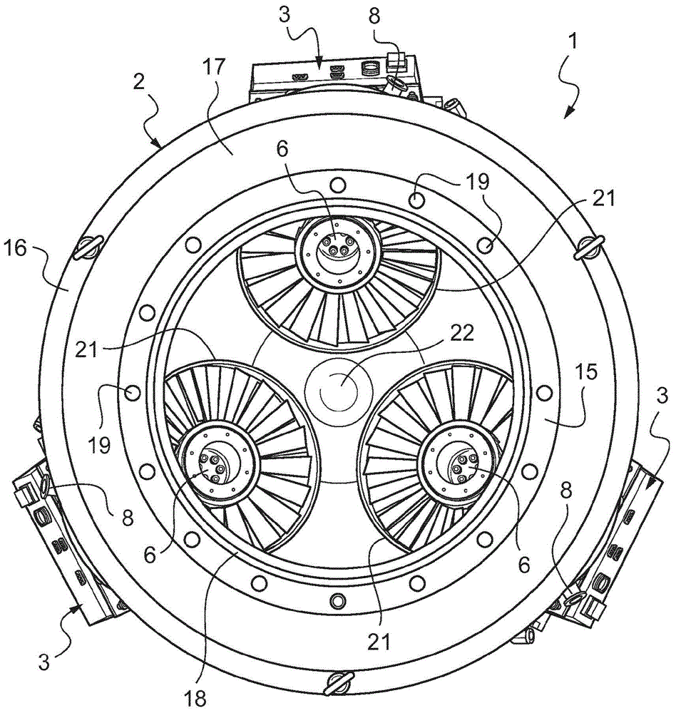
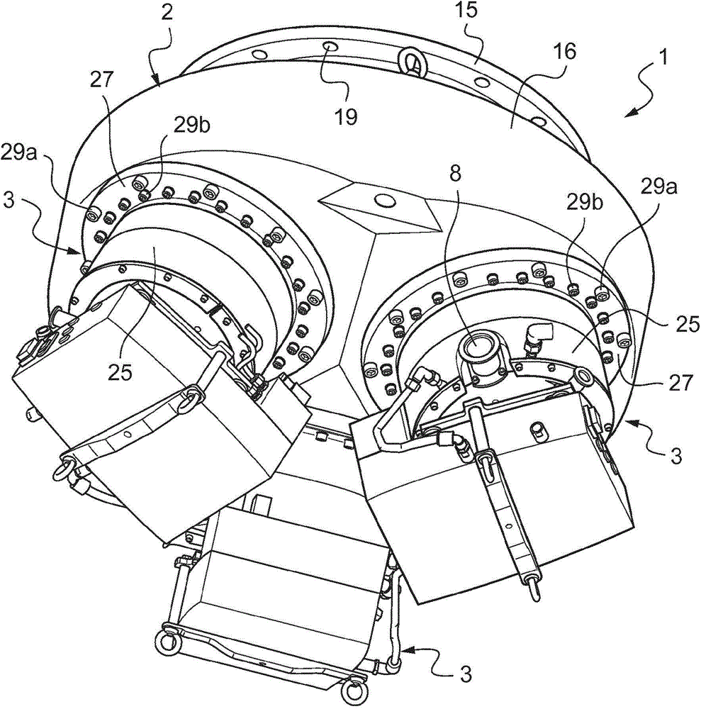
[0049] Figure 1-4 A first embodiment of the pumping device 1 is shown.

[0050] The pumping device 1 includes an adapter for a vacuum pump 2 and at least two turbomolecular vacuum pumps 3. In the example shown, the number of turbomolecular vacuum pumps 3 is three.

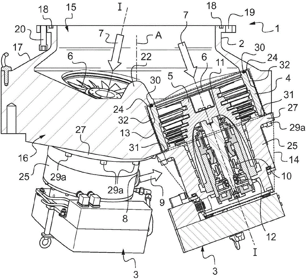
[0051] The turbomolecular vacuum pumps 3 are identical and each include a fixed part in a manner known per se, in which the rotor 5 moves along the axis of rotation I at a higher speed (see image 3 Cross-sectional view) for axial rotation.

[0052] In the illustrative example, the turbo molecular vacuum pump 3 includes a turbo molecular stage 13 and a molecular stage 14 respectively.

[0053] At the turbomolecular stage 13, the fixed part includes a housing 4 including an inlet hole 6 at the first end coaxial with the axis of rotation, through which the pumped gas 7 passes.

[0054] According to an exemplary embodiment, the rotor 5 includes an upstream portion (in the direction of the airflow) of the turbine-type blade rot...


PUM


Abstract

The invention relates to an adapter for vacuum pumps, characterized in that it comprises an annular inlet flange (15) intended to be coupled to an outlet orifice of a chamber and an outlet coupling (16) comprising at least two cylindrical outlet through-housings (21) and forming an at least partial pump casing for the case (4) of a respective turbomolecular vacuum pump (3), said turbomolecular vacuum pumps (3) being intended to be received in a respective cylindrical outlet housing (21). The invention also relates to a pumping device, characterized in that it comprises an adapter for vacuum pumps (2) as described hereinabove and at least two turbomolecular vacuum pumps (3) housed at least partially in a respective cylindrical outlet housing (21).

Description

technical field [0001] The invention relates to a turbomolecular vacuum pump coupled to a chamber for generating a high vacuum. Background technique [0002] Creating a high vacuum within the chamber requires the use of pumps that can quickly create and maintain this high vacuum. A turbomolecular type vacuum pump comprising a pump housing housing a housing and in which a rotor is driven into rotation rapidly, for example at speeds in excess of 3000 revolutions per minute, is commonly used. [0003] The pump casing includes an inlet hole coaxial with the rotor, which is coupled with the outlet hole of the chamber. Typically, the pump is fixed to a single fixing structure of the chamber, and support for the pump is provided by a single area surrounding the inlet aperture of the pump and the corresponding outlet aperture of the fixing structure. Thus, the pump housing comprises a coaxial annular coupling flange around the inlet hole, which is clamped and screwed onto the fixe...

Claims


Application Information

Patent Timeline
IPC IPC(8): F04D19/04F04D25/16F04D29/60
CPCF04D29/60F04D25/16F04D19/046F04D19/042F04D29/601
Inventor T·布里昂R·马西斯N·瓦雷纳
Owner PFEIFFER VACUUM GMBH
Why Eureka
Try Eureka