Ball joint and manufacturing method therefor

一种球窝接头、制造方法的技术,应用在连接、枢轴连接、轴承等方向,能够解决无法球部流通焊接电流等问题,达到接触面压减弱、圆滑动作的效果

Active Publication Date: 2014-09-03
THK CO LTD
View PDF5 Cites 11 Cited by
  • Summary
  • Abstract
  • Description
  • Claims
  • Application Information

AI Technical Summary

Problems solved by technology

However, since there is a resin sliding contact member between the ball portion and the cage, it is not possible to pass the welding current to the ball portion using the cage as in Patent Document 1.

Method used


Image

  • Ball joint and manufacturing method therefor
  • Ball joint and manufacturing method therefor
  • Ball joint and manufacturing method therefor

Examples


Embodiment Construction

[0031] Hereinafter, the ball joint and its manufacturing method of the present invention will be described in detail using the drawings.

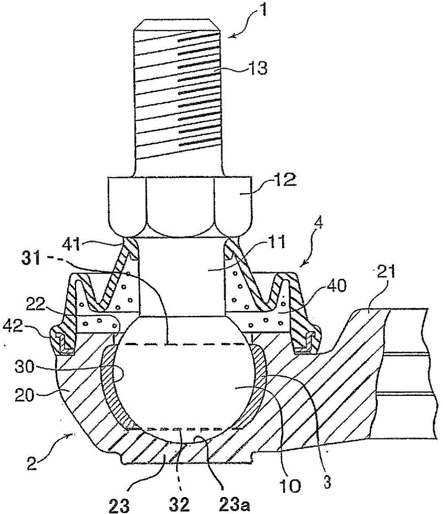
[0032] figure 1 It is a figure which shows the 1st embodiment of the ball joint manufactured by this invention. This ball joint is formed by a ball stud 1 having a ball portion 10 at the tip of a shaft member 11, a resin sliding contact member 3 that covers the ball portion 10 and is in sliding contact with the ball portion 10, and a resin sliding contact member 3 formed on the resin sliding contact member 3. The member 3 is surrounded by a retainer 2 that fixes the resin sliding contact member 3, and the ball stud 1 is connected so as to be swingable relative to the retainer 2 centering on the ball portion.

[0033]The ball stud 1 is formed by resistance welding a rod-shaped shaft member 11 to a high-sphericity bearing steel ball serving as the ball portion 10 . The shaft member 11 is formed with a flange portion 12 provided with a suppo...


PUM


Abstract

The present invention relates to a ball joint in which a holder (2) is cast with a ball (10) as a core and a shaft member (11) is electric resistance welded to the cast ball (10), and a manufacturing method therefor. A ball joint is provided with: a ball (10); a resin sliding contact member (3) which has a first opening (31) and a second opening (32) from which the spherical surface of the ball (10) is exposed in opposite directions; a holder (2) which is cast with the ball (10) and the resin sliding contact member (3) as a core and with which a blocking part (23) that is being in contact with the ball (10) protruding from the second opening (32) of the resin sliding contact member (3) is integrally molded; and a shaft member (11) which constitutes a ball stud (1) by being joined to the ball (10) exposed from the first opening (31) of the resin sliding contact member (3) by electric resistance welding after the holder (2) is cast.

Description

technical field [0001] The present invention relates to a ball joint used in a link mechanism such as a stabilizer link of an automobile, a transmission control unit, and a method for manufacturing the same. Background technique [0002] As such a ball joint, what is disclosed in Japanese Unexamined Patent Publication No. 9-189322 (Patent Document 1) is known. The ball joint disclosed in this document is composed of a ball stud having a ball at the tip of the shaft member, which is the center of swing of the link mechanism, and the largest diameter portion of the ball portion of the ball stud that covers and slides on the spherical surface of the ball portion. The contact cage constitutes. [0003] The cage is formed by casting using the spherical portion as a core, and the spherical rotation of the spherical portion is formed at the cage by using steel balls for bearings with a high sphericity as the spherical portion. Printed metal sliding contact surfaces with high sphe...

Claims


Application Information

Patent Timeline
Patent Type & Authority Applications(China)
IPC IPC(8): F16C11/06
CPCY10T29/49826Y10T403/32737F16C11/0609F16C11/0695F16C2208/00F16C11/0633F16C11/0657F16C2226/36F16C11/0685F16C11/06
Inventor 西出哲弘东海林勤庄司春树末永淳也
Owner THK CO LTD
Why Eureka
Try Eureka